element14 Community
element14 Community
    Register Log In
  • Site
  • Search
  • Log In Register
  • Community Hub
    Community Hub
    • What's New on element14
    • Feedback and Support
    • Benefits of Membership
    • Personal Blogs
    • Members Area
    • Achievement Levels
  • Learn
    Learn
    • Ask an Expert
    • eBooks
    • element14 presents
    • Learning Center
    • Tech Spotlight
    • STEM Academy
    • Webinars, Training and Events
    • Learning Groups
  • Technologies
    Technologies
    • 3D Printing
    • FPGA
    • Industrial Automation
    • Internet of Things
    • Power & Energy
    • Sensors
    • Technology Groups
  • Challenges & Projects
    Challenges & Projects
    • Design Challenges
    • element14 presents Projects
    • Project14
    • Arduino Projects
    • Raspberry Pi Projects
    • Project Groups
  • Products
    Products
    • Arduino
    • Avnet Boards Community
    • Dev Tools
    • Manufacturers
    • Multicomp Pro
    • Product Groups
    • Raspberry Pi
    • RoadTests & Reviews
  • Store
    Store
    • Visit Your Store
    • Choose another store...
      • Europe
      •  Austria (German)
      •  Belgium (Dutch, French)
      •  Bulgaria (Bulgarian)
      •  Czech Republic (Czech)
      •  Denmark (Danish)
      •  Estonia (Estonian)
      •  Finland (Finnish)
      •  France (French)
      •  Germany (German)
      •  Hungary (Hungarian)
      •  Ireland
      •  Israel
      •  Italy (Italian)
      •  Latvia (Latvian)
      •  
      •  Lithuania (Lithuanian)
      •  Netherlands (Dutch)
      •  Norway (Norwegian)
      •  Poland (Polish)
      •  Portugal (Portuguese)
      •  Romania (Romanian)
      •  Russia (Russian)
      •  Slovakia (Slovak)
      •  Slovenia (Slovenian)
      •  Spain (Spanish)
      •  Sweden (Swedish)
      •  Switzerland(German, French)
      •  Turkey (Turkish)
      •  United Kingdom
      • Asia Pacific
      •  Australia
      •  China
      •  Hong Kong
      •  India
      •  Korea (Korean)
      •  Malaysia
      •  New Zealand
      •  Philippines
      •  Singapore
      •  Taiwan
      •  Thailand (Thai)
      • Americas
      •  Brazil (Portuguese)
      •  Canada
      •  Mexico (Spanish)
      •  United States
      Can't find the country/region you're looking for? Visit our export site or find a local distributor.
  • Translate
  • Profile
  • Settings
Hardware Hacking
  • Challenges & Projects
  • Project14
  • Hardware Hacking
  • More
  • Cancel
Hardware Hacking
Blog BattPackHack #2 : A Functional Prototype
  • Blog
  • Forum
  • Documents
  • Events
  • Polls
  • Files
  • Members
  • Mentions
  • Sub-Groups
  • Tags
  • More
  • Cancel
  • New
Join Hardware Hacking to participate - click to join for free!
  • Share
  • More
  • Cancel
Group Actions
  • Group RSS
  • More
  • Cancel
Engagement
  • Author Author: dubbie
  • Date Created: 26 Jun 2020 4:38 PM Date Created
  • Views 1059 views
  • Likes 5 likes
  • Comments 3 comments
  • battery pack
  • hardwarehackingch
  • dc-dc convertor
  • protoboard
Related
Recommended

BattPackHack #2 : A Functional Prototype

dubbie
dubbie
26 Jun 2020
image

Hardware Hacking

Enter Your Electronics & Design Project for a chance to win a $200 shopping cart!

Submit an EntrySubmit an Entry  Back to homepage image
Project14 Home
Monthly Themes
Monthly Theme Poll


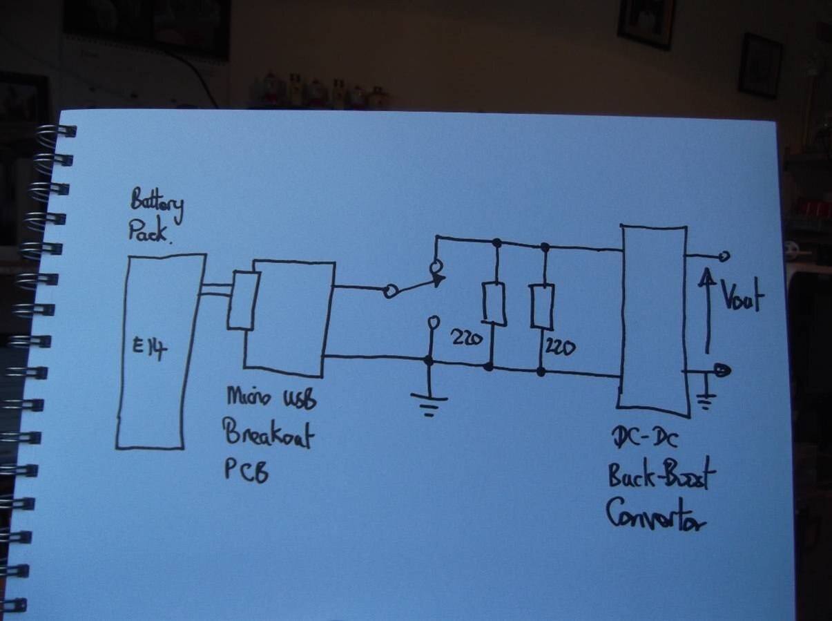
Having completed and glued together the battery holder to the prototyping board I have now created a functional working prototype. The cable from the E14 battery pack has been plugged into a micro USB breakout PCB to gain access to the power connections. I have not cut the micro USB plug off the battery pack so that I can still use it as a mobile phone charger should I want to at some time in the future. In order to make the battery pack work continuously a minimum current of approximately 50 mA must be taken and as the battery output is about 5 V this means a resistive load of 100 Ohms. As I do not have any 100 Ohm resistors I have used two 220 Ohm resistors in parallel which gives me the 100-ish Ohm resistance, with the added benefit of twice the heat dissipation. As this load has to be taken when in use then an ON/OFF switch is also required otherwise the battery would not last very long. The two resistors and the slide switch have been soldered together on a piece of stripboard which isn't that pretty but it is functional. The switched battery connection is then made directly to the input of the DC-DC convertor with soldered connections - mainly because the micro USB connector fell off when I was playing around with it -  a drawback of surface mount micro USB connectors. The circuit diagram is shown below.


image


The working prototype is illustrated next. The output voltage can be varied from a low of 0.5V all the way up to 25.8V although I'm not sure of the maximum output current at these points. There is also going to be some power loss as heat in this circuit, especially in the two 220 Ohm resistors which become warm to the touch after only a few seconds. I will have to keep an eye on that issue.


You don't have permission to edit metadata of this video.
Edit media
x
image
Upload Preview
image


One of the stick on rubber feet fell off the prototyping board as I was doing the filming; old glue and hot temperatures I expect. I'll have to glue it back on with better glue, or even with a small screw.


I have an objective of designing and 3D printing a casing for all the electronics on the top of the BattPackHack to make it look nicer but the DC-DC convertor is an awkward shape to cover so this might be delayed. I also want to add some sort of built-in voltmeter as well so I might concentrate on that rather than the 3D printed case. If the weather's nice I'll be out in the garden although it is 28 C today which is a bit too hot for me.


Dubbie

  • Sign in to reply

Top Comments

  • DAB
    DAB over 5 years ago +1
    Very interesting project. DAB
  • Fred27
    Fred27 over 5 years ago +1
    Looks like a useful project. Your diagram makes it look like on of the switch positions shorts the battery output to ground. I'm hoping that's just a mistake in the diagram rather than your circuit.
  • dubbie
    dubbie over 5 years ago in reply to Fred27

    Fred,


    Well spotted. Just a slip of the pen as I was drawing in the lines for the two resistors, the ground connection ot the switch isn't there. If it was I'd probably need a new battery!


    Dubbie

    • Cancel
    • Vote Up 0 Vote Down
    • Sign in to reply
    • More
    • Cancel
  • Fred27
    Fred27 over 5 years ago

    Looks like a useful project. Your diagram makes it look like on of the switch positions shorts the battery output to ground. I'm hoping that's just a mistake in the diagram rather than your circuit.

    • Cancel
    • Vote Up +1 Vote Down
    • Sign in to reply
    • More
    • Cancel
  • DAB
    DAB over 5 years ago

    Very interesting project.


    DAB

    • Cancel
    • Vote Up +1 Vote Down
    • Sign in to reply
    • More
    • Cancel
element14 Community

element14 is the first online community specifically for engineers. Connect with your peers and get expert answers to your questions.

  • Members
  • Learn
  • Technologies
  • Challenges & Projects
  • Products
  • Store
  • About Us
  • Feedback & Support
  • FAQs
  • Terms of Use
  • Privacy Policy
  • Legal and Copyright Notices
  • Sitemap
  • Cookies

An Avnet Company © 2025 Premier Farnell Limited. All Rights Reserved.

Premier Farnell Ltd, registered in England and Wales (no 00876412), registered office: Farnell House, Forge Lane, Leeds LS12 2NE.

ICP 备案号 10220084.

Follow element14

  • X
  • Facebook
  • linkedin
  • YouTube