element14 Community
element14 Community
    Register Log In
  • Site
  • Search
  • Log In Register
  • About Us
  • Community Hub
    Community Hub
    • What's New on element14
    • Feedback and Support
    • Benefits of Membership
    • Personal Blogs
    • Members Area
    • Achievement Levels
  • Learn
    Learn
    • Ask an Expert
    • eBooks
    • element14 presents
    • Learning Center
    • Tech Spotlight
    • STEM Academy
    • Webinars, Training and Events
    • Learning Groups
  • Technologies
    Technologies
    • 3D Printing
    • FPGA
    • Industrial Automation
    • Internet of Things
    • Power & Energy
    • Sensors
    • Technology Groups
  • Challenges & Projects
    Challenges & Projects
    • Design Challenges
    • element14 presents Projects
    • Project14
    • Arduino Projects
    • Raspberry Pi Projects
    • Project Groups
  • Products
    Products
    • Arduino
    • Avnet Boards Community
    • Dev Tools
    • Manufacturers
    • Multicomp Pro
    • Product Groups
    • Raspberry Pi
    • RoadTests & Reviews
  • Store
    Store
    • Visit Your Store
    • Choose another store...
      • Europe
      •  Austria (German)
      •  Belgium (Dutch, French)
      •  Bulgaria (Bulgarian)
      •  Czech Republic (Czech)
      •  Denmark (Danish)
      •  Estonia (Estonian)
      •  Finland (Finnish)
      •  France (French)
      •  Germany (German)
      •  Hungary (Hungarian)
      •  Ireland
      •  Israel
      •  Italy (Italian)
      •  Latvia (Latvian)
      •  
      •  Lithuania (Lithuanian)
      •  Netherlands (Dutch)
      •  Norway (Norwegian)
      •  Poland (Polish)
      •  Portugal (Portuguese)
      •  Romania (Romanian)
      •  Russia (Russian)
      •  Slovakia (Slovak)
      •  Slovenia (Slovenian)
      •  Spain (Spanish)
      •  Sweden (Swedish)
      •  Switzerland(German, French)
      •  Turkey (Turkish)
      •  United Kingdom
      • Asia Pacific
      •  Australia
      •  China
      •  Hong Kong
      •  India
      •  Korea (Korean)
      •  Malaysia
      •  New Zealand
      •  Philippines
      •  Singapore
      •  Taiwan
      •  Thailand (Thai)
      • Americas
      •  Brazil (Portuguese)
      •  Canada
      •  Mexico (Spanish)
      •  United States
      Can't find the country/region you're looking for? Visit our export site or find a local distributor.
  • Translate
  • Profile
  • Settings
Hardware Hacking
  • Challenges & Projects
  • Project14
  • Hardware Hacking
  • More
  • Cancel
Hardware Hacking
Blog Pong is Alive
  • Blog
  • Forum
  • Documents
  • Events
  • Polls
  • Files
  • Members
  • Mentions
  • Sub-Groups
  • Tags
  • More
  • Cancel
  • New
Join Hardware Hacking to participate - click to join for free!
  • Share
  • More
  • Cancel
Group Actions
  • Group RSS
  • More
  • Cancel
Engagement
  • Author Author: ralphjy
  • Date Created: 7 Jun 2020 11:11 PM Date Created
  • Views 3077 views
  • Likes 12 likes
  • Comments 13 comments
  • ay-3-8500-1
  • pong on a chip
  • hardwarehackingch
Related
Recommended

Pong is Alive

ralphjy
ralphjy
7 Jun 2020

As part of the Hardware Hacking Challenge I thought that I'd try to resurrect a Pong game that I built back in 1978.  My intro blog is here: Pong Game Circa 1978


Since it came out of my junk box and seemed to be in poor condition I thought that I probably should have proof of life before I invested too much effort in restoring it.  I was somewhat surprised that the 30 AWG wirewrap wire that I had used had oxidized and become brittle.  Some of the wires were actually broken.  I still use 28 AWG wire of the same vintage and the unused wire seems like new.  I guess maybe the wire may have reacted with the metallization of the wirewrap pins.  Anyway, I decided I should rebuild the circuit from scratch - just reusing the ICs and the crystal.


So, I cut the circuit board out of the case (who used connectors back then image).


Top of the board:

image


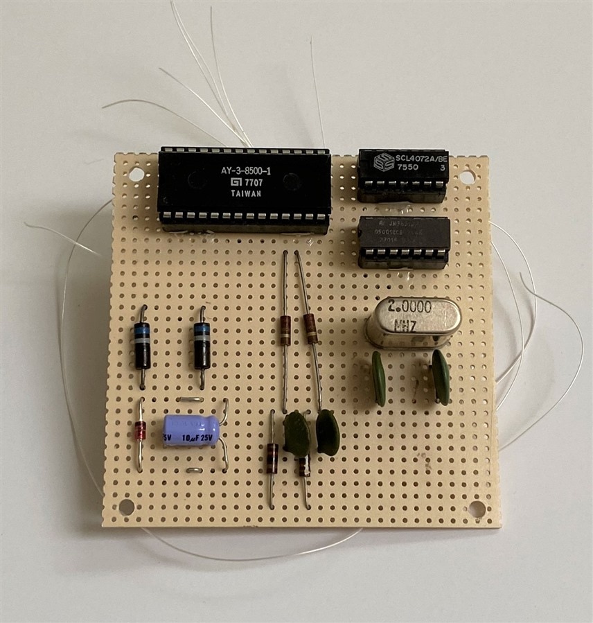
  • Pong chip AY-3-8500-1 (-1 for NTSC)  Date code 7707
  • 4072 CMOS Dual 4 input NOR
  • 4001 CMOS Quad 2 input NOR (might be a 4011 Quad NAND - can't read the marking)
  • 2MHz crystal
  • 6.3V zener - I had used 9V batteries for power (I probably could have run the parts directly but the typical voltage for the Pong chip is +6V to +7V)


The bottom of the board:  You can see the blackened wire ends wrapped on the pins.

image


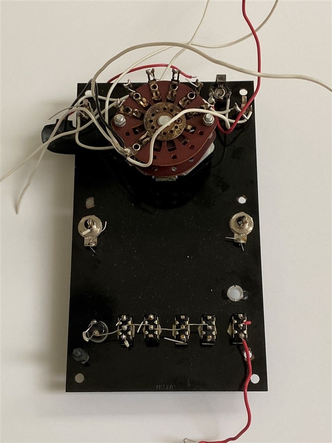
Switches and jacks viewed from inside the case:

image


To verify life I thought that I'd just power it up and verify the clock circuit and that the video sync and composite outputs were working.


2 MHz oscillator waveform:

image


Video sync:

image


Composite video:

image


So looks good to proceed.  Hope to have a functioning game soon.  I just realized that I'll have to scare up a composite monitor......

  • Sign in to reply

Top Comments

  • dubbie
    dubbie over 5 years ago +4
    It is encouraging to see that technology this old can still be brought back to life. I was intrigued by the wire wrap as I started in my design days using wire wrap, mainly because it didn't use a soldering…
  • ralphjy
    ralphjy over 5 years ago in reply to dubbie +4
    We used to build test systems with large multi slot backplanes. Used a lot of automation back then. Too bad I don’t have pictures - the wire wrap machines were essentially large robots moving the wire…
  • jw0752
    jw0752 over 5 years ago +3
    Hi Ralph, This looks like fun. Another cause of the blackening might have been storage. Some papers and other materials will have a small amount of sulfur compounds which can cause blackening. Even if…
  • HDCase
    HDCase over 1 year ago in reply to ralphjy

    Thanks for your reply. I am planning to stick with the original design, jumper wires and all!!Grinning

    image

    • Cancel
    • Vote Up 0 Vote Down
    • Sign in to reply
    • More
    • Cancel
  • ralphjy
    ralphjy over 1 year ago in reply to HDCase

    Hi, apologies but I can't be much help with the spec on the zener diode that I used.  I did that project quite a while ago and my files are on a computer that is currently offline.  I had reused that diode from the original very old circuit, so I may or may not have had a part number for it.

    I would guess that the power rating was in the 400-500mW range and the tolerance was 2-5%.  It was not a standalone implementation (no speaker, audio amplifier, or rf modulator) - I just generated a line level audio output and a composite video output to a compatible monitor/TV, so my total power was under 300mW (less than 50mA).

    It seems odd that you would have 6 zener diodes, but you certainly have more circuitry and a larger power requirement.  Unless you are trying to stay with the original circuit - maybe you should just use some voltage regulators or a wall wart (not sure how many different voltages you need).

    If you need to stay with zeners, a 5% tolerance on the should be okay.  Choose the power rating based on the required load current and set the series resistor so that you have enough zener current to maintain regulation at maximum load current.

    • Cancel
    • Vote Up 0 Vote Down
    • Sign in to reply
    • More
    • Cancel
  • HDCase
    HDCase over 1 year ago

    Hi Ralphjy, I'm trying to revive a commercial implementation of the same pong chip. I've never worked with Zener diodes before and this console has 6! Aside from the voltage, can you tell me the specs of your diodes. And do you know if there is tolerance in using the wrong ones?

    image

    • Cancel
    • Vote Up 0 Vote Down
    • Sign in to reply
    • More
    • Cancel
  • dubbie
    dubbie over 5 years ago in reply to ralphjy

    Ralph,


    Yes, I do remember the 74??LS181 ALU chips. I toyed with the idea of making my own computer based on them but it was on the cusp of programmable logic at the time so I looked to the future and did PLDs with my students instead. It was certainly easier.

    • Cancel
    • Vote Up 0 Vote Down
    • Sign in to reply
    • More
    • Cancel
  • ralphjy
    ralphjy over 5 years ago in reply to dubbie

    You're a real youngster then....  The first serious computer that I started working on was built using 74181 ALU chips and PMOS memory (negative logic back then meant negative voltage and we used a lot of voltage shifters between the memory and processing system).  I think I still have hand drawn schematics somewhere and the logic drafting templates.  I wish that I had kept some of the PCBs and parts.

    • Cancel
    • Vote Up +1 Vote Down
    • Sign in to reply
    • More
    • Cancel
>
element14 Community

element14 is the first online community specifically for engineers. Connect with your peers and get expert answers to your questions.

  • Members
  • Learn
  • Technologies
  • Challenges & Projects
  • Products
  • Store
  • About Us
  • Feedback & Support
  • FAQs
  • Terms of Use
  • Privacy Policy
  • Legal and Copyright Notices
  • Sitemap
  • Cookies

An Avnet Company © 2025 Premier Farnell Limited. All Rights Reserved.

Premier Farnell Ltd, registered in England and Wales (no 00876412), registered office: Farnell House, Forge Lane, Leeds LS12 2NE.

ICP 备案号 10220084.

Follow element14

  • X
  • Facebook
  • linkedin
  • YouTube