


Getting the board running
So, after receiving my SQRL Acorn cryptominer board, the first thing I needed to do was power it up and connect to it. I decided that to start with it might be impractical to have it located in a PCIe slot inside my PC as that would make it physically inaccessible.
Power
Luckily, it seems that when mining away it requires more power than a PCIe (or m.2) slot can provide so there is an external power connector on the PCIe mounting card that came with it. This is intended to take 12V from a standard PC power supply via a 6-pin PCIe power connector. I don't have one of these to hand but it looked uncannily like some Molex Mini-fit connectors that I did have. The 6 pins are just arranged as 3 ground and 3 12V supply pins and these are connected together on the SQRL PCIe board. I took a 4-pin Molex Mini-fit connector and added just two pins to the housing - one ground and one 12V. I wasn't intending to do anything that needed much power so I thought that this - connected to a decent 12V supply should be fine for my initial investigation. Carefully supplying 12V with some current limiting just in case and the board whirred into life.
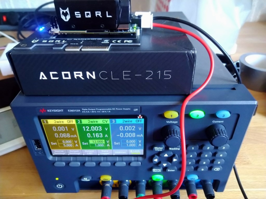
Some LEDs were blinking showing me that it was running whatever bitstream had been programmed into it for cryptomining. It was drawing only 163mA so I assume this is just sitting there waiting for instructions. The onboard fan is small and therefor fairly high speed and noisy. With that low power consumption and no noticeable heat, I decided to disconnect it for a bit of peace and quiet.
An FPGA with someone else's pointless bitstream is no use at all so onto the first challenge. Can I get JTAG working?
Connectors
The connector are slightly unusual. The JTAG connector and IO next to it are fine pitch connectors that looks like they have to be slid in from the side but are actually pressed down onto the board. They're Molex PicoEZmate and were luckily available in premade cables. That meant I could buy one cable and cut it in half to use one for JTGA and the other for the IO connector next to it. Product LinkProduct Link Note the now disconnected fan lead!
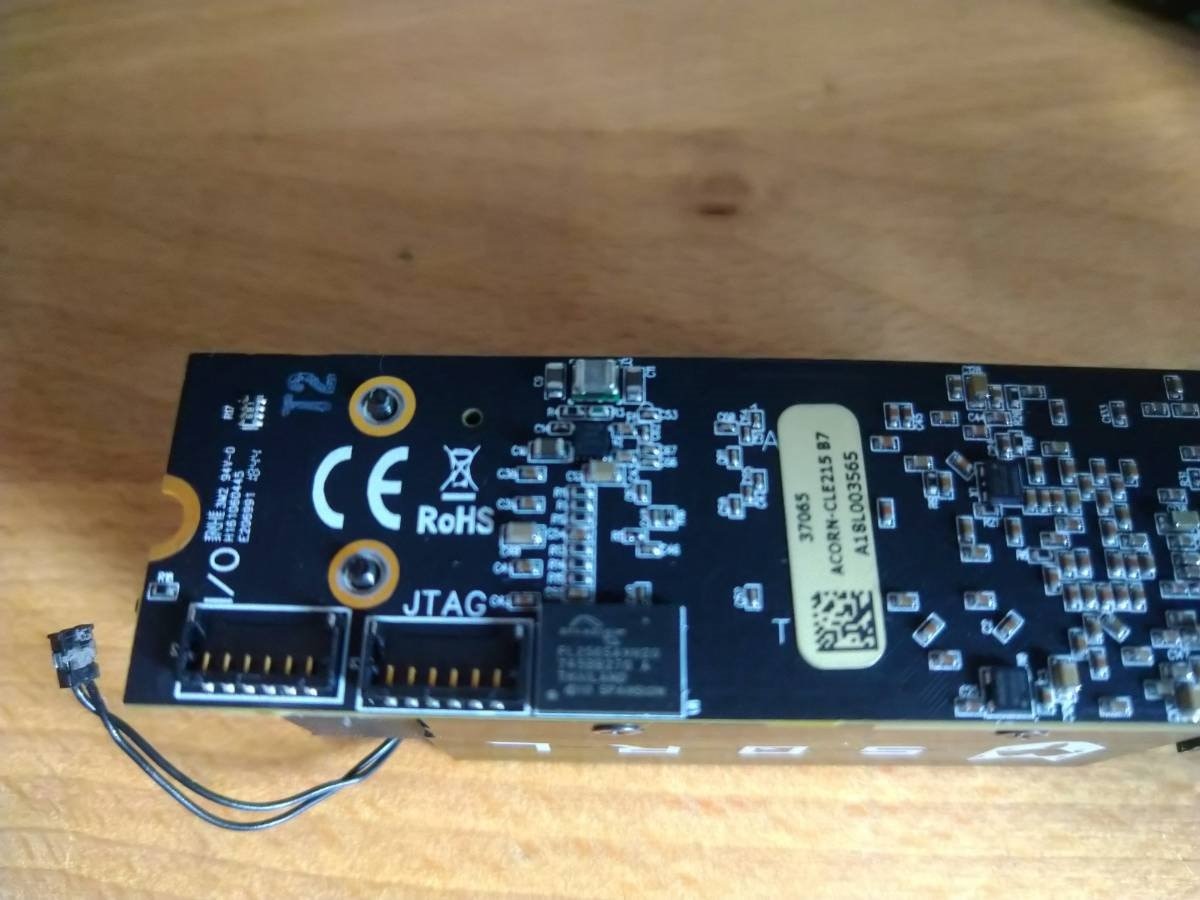
Under the heatsink there is also another IO connector. This one is a 20-pin Hirose DF52 connector. This unfortunately does have to be crimped and assembled. It's a job I'm not looking forward to. The strength of this board is not the IO. There are better boards if you want that. It's in the fact that I might be able to communicate with it over PCIe. I bought these connectors anyway, but I'm in no rush to assemble them for now. Product LinkProduct Link
JTAG
With a nicely labelled 6-pin JTAG port at least I didn't have to start randomly probing or guessing at test points. To be honest if it didn't have this I probably wouldn't have taken it project on.
Power and ground
This was pretty simple. There is a small 2-pin connector for the fan (now disconnected) and a quick continuity check with a multimeter shows that two of the JTAG connector pins are the same. The supply is not for powering the device, but so that the JTAG knows what levels the device is using. That leave four more unlabelled pins to work out. It didn't seem to match any obvious standards. Time for some brute force.
TCK, TDO, TDI and TMS
So there are 24 combinations possible for the remaining 4 pins. It wouldn't be insurmountable to try them all, but there has to be a slightly better way. If it's one thing that computers are good at it's blindly following instructions. JTAGenum to the rescue! By the way, this is a great article on reverse engineering that steered me towards JTAGenum. Worth a read.
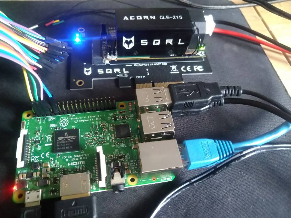
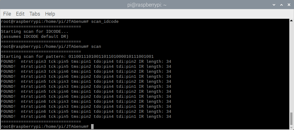
JTAGenum will simply try all the combinations it can for the four pins (and also NTRST). It is bit-banged so can be a bit slow. Also apparently it can be a bit hit-and-miss whether it works with a certain device, but I had nothing to lose. I fired it up and tried the three available commands. loopback_check gave nothing away. scan_idcode also did nothing. However scan gave some promising output. 12 combinations gave the sort of response that suggested they might be valid. It only halved my work, but I can imagine it's even more useful if you aren't sure you have a JTAG port at all.
With some educated guesses and a little bit of experimentation - we had JTAG access. It turned out the the magic combination (starting from the furthest pin from the IO port and working towards it) is:
| Pin | Signal |
|---|---|
| 1 | GND |
| 2 | TCK |
| 3 | TDO |
| 4 | TMS |
| 5 | TDI |
| 6 | 3.3V |
Vivado can see the board!
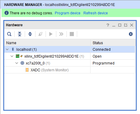
If you're at all familiar with Vivado then you will know why this fills me with joy. My Digilent HS2 debugger is connected up to the relevant JTAG pins and can identify the Artix 7 xc7a200t device on the board. There's no nothing stopping me creating a bitstream from a Vivado project and uploading it to the board over JTAG. The next question is what. I know where the JTAG pins connect, but what about the others? If the pins of the FPGA were physically accessible it would be possible to trace them - either visually or using a continuity tester. However even if I removed the heatsink, this is a BGA chip. There would be nothing to see.
There are way to do this - including a very clever trick which makes every pin an UART that shouts out a different character. I'll leave that for another blog post though.