The Smart Room Project - Current Phase
1. Introduction
Hi! In this blog I'll be showing the basics I did for my smart room all based on an Arduino MKR1000. I am currently a student still living with my parents so all of the focus will be towards my bedroom. This is something I started a couple of months ago and work on it every now and then in my free time (of which there isn't a lot), but nevertheless, I managed to get it to a point where it's actually really useful to me. I'll be covering everything here from hardware I used to the software I've made. Just want to point in the beginning that this project involves working with dangerous voltages 220V that can cause serious injuries. Let's begin with my initial plan, why I did what I did, how I did it and in the end what I plan on doing later on.
2. Plan and Inspiration
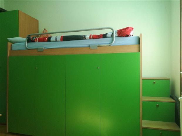
The main inspiration for me to get into this project was my bed and here is why. I got a bed that's on the "second story" with storage space underneath it.
There is no power near it and the light switch is beyond the reach of me of whatever I did (At one point I would keep a skiing pole near my bed so I can turn off the light). This all causes a problem because if I wanted to read something before the sleep I had a few options, use my phone/flashlight as a source of light, somehow mount a lamp with a long cable on top of my cupboard, get up after I'm finished with reading go down turn off the light and climb back up or of course make it so I can control the lights remotely. The obvious winner was the last option.
With an idea in mind it was time to plan out the basics I wanted to do and just go at it. My main goal was to be able to remotely control the blinds and lights while leaving room for upgrading everything further down the line when I have free time. For remote controlling everything I went with 2 approaches, an IR Remote and I also made an Android app from scratch, one thing that turned out also was that I can also use my PC to control the lights, but I'll get into that later on. Since I wanted to use my phone as well I had 2 options, either WiFi or Bluetooth. I went WiFi since I've never worked with it and my phone is always connected to it anyway while it's in the house. As the brain that controls everything I went with the Arduino MKR1000 because I already had one and it has integrated WiFi on it with loads of pins for further upgradeability so It was a perfect candidate for this. I'll go now into the hardware I've used.
3. Hardware
There are a few things to cover here, I'll begin with the main unit that controls everything, and continue down the line with switches for blinds/lights, how I modified a lamp to work with the system as well as an universal box with a plug that I made which can control anything that can be plugged into it.
Main Box
As I've already said the main part is the Arduino MKR1000, while the main module is an 8 channel relay board that I got for around 10$ as well as an IR Remote set for around 4$. Besides that I used a lot of cable around the room, some switches as well as fuses and a small photoresistor for automatic lights. Here is the schematic of the main unit for the room:
All of the appliances now get connected by connecting one of the wires to a relay and the other to the end of the switch. I'll say it one more time, if you plan on attempting anything of this nature be aware of things you are working with because they can cause serious injury/death, I'm not recommending anyone to try out their own and you would be doing this on your own risk. I put in series with all of the relays a fuse and a switch, the reason for this is safety and experimenting the idea being having the switches which would turn off that channel if I want to change something fast without turning off the breaker. Both the switches and fuses turned out to be a really smart edition since in one of my first tests I connected something wrong and well:
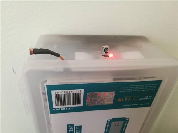
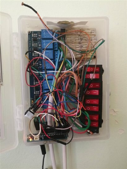
That black color on the top is from one of the fuses doing its job and exploding pretty much, but because of it nothing else got damaged and because I used good insulated switches I wasn't exposed to any harm while flipping the breaker. I disconnected everything then and reconnected everything, and when trying out again, everything looked great (nothing exploded this time). So again, be careful and take your time if you're doing this, I got lucky for the most part with this. The picture above shows the box which holds all of the electronics, I used what I had on hand, and well this is something I plan on changing for sure, since it's an incredible mess inside.
While it looks like a mess (because it is for the most part), all of the wires that are connected to absolutely anything are very well attached to where they need to be or insulated so they don't cause any damage, there are a few free wires from unused fuses that are pretty hard to get out now. Besides the things I've said until now, I've added 2 more things and those are a power switch for the Arduino itself as well as a jack for powering the Arduino, to power it, I used some old 5V charger I had laying around and it worked without any problems. One thing I made sure was that all of the cables with 220V were firmly secured so they couldn't be pulled out on accident causing problems, to solve this I used these cable holders (I don't know the term for them in English sorry).
I found them to work extremely well for me, when tightened there is no way for cable to go loose, the whole box will fall off the wall before one of the cables is pulled out on it's own. That would round up everything there is about the main box, and the thing that took the longest amount of time to do. I'll go now into the switches that I've modified to work with this.
Switches and lamp
For now I've modified 2 switches to work with my system, but have currently only integrated one of them. The thing I do to integrate a switch is, take it apart, and attach a cable in parallel to the switch. This way any of the 2 ways can be used to turn on the lights for example, but both need to be off for something to be off. There is a thing to look out for here though, that is with 3 state switches like I am using for the blinds, we can connect it in such a way that the blinds both want to go up and down in the same time (by leaving and forgetting the blinds physical switch on up and trying to bring them down by relay for example). This can cause serious problems and fry things so be careful if and how you want to integrate this, the blinds on my window have some kind of a protection against this but again be careful with that if you attempt anything similar yourself.
This is the blinds switch itself that I wired up, on the left is the 4 wire cable going to the blinds, the dark gray cable on the right is the power cord, and the white cable on the right is the cable which goes into the main box and then to the relays. The light switch is mounted in the wall but the principle is exactly the same as this, a 3 wire cable one "live" wire and two wires from the 2 bulbs from my light.
This light switch is the thing that is not yet integrated, for the wireless light I currently use a big lamp I have in the room (I usually use it for light, since I like how it light up the room better rather than the overhead lights). To use the lamp with the system what I did is cut one of the 2 wires that it uses for power and connected that split wire to the relay in the main box and that would be it. This means if the system is down for some reason I can't use the lamp but I always have the overhead lights. Next to cover is the universal box.
Universal Box
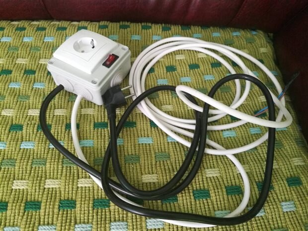
I made this with an intention for using it for a small room heater that I have. I didn't want to cut the cable as I did with the lamp so I made this box with it's own switch and fuse inside that can be controlled by connecting to the relay. One thing to point out since I designed this with an intention to use for a heater rather than the 5A fuses I uses in the main box I put a stronger 10A fuse in here since the heater is around 1800W.
On the front of the box is a standard socket and a switch for controlling this channel, the black cable is the power cable, while the white cable is the cable that goes the main box and is controlled by the relay. This is something I would like to do to all of the sockets in my room, but keeping it all small in wall would require a lot of work and time. With that, that would be all of the hardware covered that I've used for now, later on I'll show what I plan on adding in the feature, now it's time to go to software.
3. Software
I'll split the software into 2 different parts, in the first part I'll cover programming the Arduino with which this whole system becomes usable using a computer or the IR Remote and in the second part I'll cover the Android app I made and am still expanding and learning Android programming on as I go on. Let's begin.
Arduino MKR1000 Code
To begin let's start with the list of things I had to accomplish with this code first:
- Connecting to the Internet
- Getting data from internet (I haven't had time to do anything with any feedback yet unfortunately, so the system can only receive controls for now, but I plan on changing that soon)
- Interpreting the IR Remote
- Measuring light levels with the photoresistor
- Controlling all of the relays
The biggest problem by far was the IR remote, the code itself is very simple, but there was a problem with using the standard IR Remote library with the MKR1000 so I had to look around online until I found a library that works with my board. My whole code is built on of the MKR1000 example codes for WiFi. Here is the whole code, after which I'll go and explain some of the parts.
#include <IRremote.h>
#include <SPI.h>
#include <WiFi101.h>


IPAddress ip(192, 168, 1, 6); //Static IP
int button_hex=NULL,button,previous=NULL,last_button_pressed,left_light=0,right_light=0,t1=0,t2=0;
int automatic_lights_button=0;
int lamp=0;
int lumination=0;
int relay[8][2];
const int lumination_threshold = 600; // the lumination level at which the light sensor is triggered
const int RECV_PIN = 7;     // receiving pin for the IR remote
char ssid[] = "Your network SSID";      // your network SSID (name)
char pass[] = "Your network Password";   // your network password
int keyIndex = 0;
int status = WL_IDLE_STATUS; //status of wifi


IRrecv irrecv(RECV_PIN);
decode_results results;


WiFiServer server(80);


void setup(){


  Serial.begin(9600);
  irrecv.enableIRIn();
  irrecv.blink13(true);

  if (WiFi.status() == WL_NO_SHIELD) {
  //  Serial.println("WiFi shield not present");
    // don't continue:
    while (true);
  }


  WiFi.config(ip); //Setting the static IP for the Arduino

  while ( status != WL_CONNECTED) {
    Serial.print("Attempting to connect to SSID: ");
    Serial.println(ssid);
    status = WiFi.begin(ssid, pass);
    delay(10000);
  }


  server.begin();


  printWifiStatus();
  Serial.println("Setting up pins and relays.");


  pinMode(A2,INPUT); //lumination sensor
  pinMode(0,OUTPUT);
  pinMode(1,OUTPUT);
  pinMode(2,OUTPUT);
  pinMode(3,OUTPUT);
  pinMode(4,OUTPUT); //Lamp
  pinMode(5,OUTPUT);
  pinMode(6,OUTPUT);
  pinMode(8,OUTPUT);

  for(int i=0;i<8;i++)
  {
    relay[i][0]=i;
    relay[i][1]=-1;
  }


  digitalWrite(0,HIGH);
  digitalWrite(1,HIGH);
  digitalWrite(2,HIGH);
  digitalWrite(3,HIGH);
  digitalWrite(4,HIGH);
  digitalWrite(5,HIGH);
  digitalWrite(6,HIGH);
  digitalWrite(8,HIGH);

  Serial.println("All relays set to zero");

}


int button_pressed()
{
  int x;
  if (irrecv.decode(&results))
  {
        irrecv.resume();
        x=results.value;
        //Serial.println(x, HEX);
        return x;
  }
  else return NULL;

  }


int button_decode(int button1)
{
  switch(button1)
  {
    case 0xFF6897:
          Serial.println(1);
          return 1;
    case 0xFF9867:
          Serial.println(2);
          return 2;
    case 0xFFB04F:
          Serial.println(3);
          return 3;
    case 0xFF30CF:
          Serial.println(4);
          return 4;
    case 0xFF18E7:
          Serial.println(5);
          return 5;
    case 0xFF7A85:
          Serial.println(6);
          return 6;
    case 0xFF10EF:
          Serial.println(7);
          return 7;
    case 0xFF38C7:
          Serial.println(8);
          return 8;
    case 0xFF5AA5:
          Serial.println(9);
          return 9;
    case 0xFF42BD:
          Serial.println("*");
          return 10;
    case 0xFF4AB5:
          Serial.println(0);
          return 11;
    case 0xFF52AD:
          Serial.println("#");
          return 12;
    case 0xFF629D:
          Serial.println("UP");
          return 13;
    case 0xFFA857:
          Serial.println("DOWN");
          return 14;
    case 0xFF02FD:
          Serial.println("OK");
          return 16;
    case 0xFF22DD:
          Serial.println("LEFT");
          return 16;
    case 0xFFC23D:
          Serial.println("RIGHT");
          return 17;
    case 0xFFFFFFFF:
          Serial.println("Still pressed");
          return 100;
    case NULL:
          return 0;
    default:
          Serial.println(button1,HEX);
          Serial.println("Button not recognized");
          return NULL;
    }
  }


void printWifiStatus() {
  // print the SSID of the network you're attached to:
  Serial.print("SSID: ");
  Serial.println(WiFi.SSID());


  // print your WiFi shield's IP address:
  IPAddress ip = WiFi.localIP();
  Serial.print("IP Address: ");
  Serial.println(ip);


  // print the received signal strength:
  long rssi = WiFi.RSSI();
  Serial.print("signal strength (RSSI):");
  Serial.print(rssi);
  Serial.println(" dBm");
}


void relays(int button1)
{
  switch(button1)
  {
    case 1:
        Serial.println("Changing state of relay 1 - Lamp");
        relay[1][1]*=-1;
        break;

    }
  }


int counter=0;


void android_app(WiFiClient client)
{
    Serial.println("new client");           // print a message out the serial port
    String currentLine = "";                // make a String to hold incoming data from the client
    while (client.connected()) {            // loop while the client's connected
      if (client.available()) {             // if there's bytes to read from the client,
        char c = client.read();             // read a byte, then
       // Serial.write(c);                    // print it out the serial monitor
        if (c == '\n') {                    // if the byte is a newline character


          // if the current line is blank, you got two newline characters in a row.
          // that's the end of the client HTTP request, so send a response:
          if (currentLine.length() == 0) {
            // HTTP headers always start with a response code (e.g. HTTP/1.1 200 OK)
            // and a content-type so the client knows what's coming, then a blank line:
            client.println("HTTP/1.1 200 OK");
            client.println("Content-type:text/html");
            client.println();
            client.print("It works");
            client.print("<br>");
            // The HTTP response ends with another blank line:
            client.println();
            // break out of the while loop:
            break;
          }
          else {      // if you got a newline, then clear currentLine:
            currentLine = "";
          }
        }
        else if (c != '\r') {    // if you got anything else but a carriage return character,
          currentLine += c;      // add it to the end of the currentLine
        }


        // Check to see if the client request was "GET /H" or "GET /L":
        if (currentLine.endsWith("GET /H")) {
           automatic_lights_button=0;
           if(lamp==0)
           {
            digitalWrite(4,LOW);
            lamp=1;
            client.print("Lamp on");
           }
           else
           {
            digitalWrite(4,HIGH);
            lamp=0;
            client.print("Lamp off");
           }
        }


        if (currentLine.endsWith("GET /U")) {
           digitalWrite(1,HIGH);
           digitalWrite(0,LOW);
        }


        if (currentLine.endsWith("GET /S")) {
           digitalWrite(1,HIGH);
           digitalWrite(0,HIGH);
        }


        if (currentLine.endsWith("GET /D")) {
           digitalWrite(0,HIGH);
           digitalWrite(1,LOW);
        }


        if(currentLine.endsWith("GET /A"))
        {
          if(automatic_lights_button==0)
          {
            automatic_lights_button=1;
            client.print("Automatic Lights Turned On!");
            }
            else
            {
              automatic_lights_button=0;
              client.print("Automatic Lights Turned Off!");
              }
          }


      }
    }
    // close the connection:
    client.stop();
  }


void automatic_light(WiFiClient client)
{
    lumination = analogRead(A2);
    delay(100);
    Serial.println(lumination);
    if(lumination<lumination_threshold && lamp==0)
    {
      digitalWrite(4,LOW);
      lamp=1;
      client.print("Lamp on");
      }

  }


void loop(){


  WiFiClient client = server.available();
  button_hex = button_pressed();
  button = button_decode(button_hex);


  if (client) {
    android_app(client);
  }


  if(automatic_lights_button==1)
  {
    automatic_light(client);
    }

  if(button!=100 && button!=NULL)
    {
      last_button_pressed=button;
    }


  if(button==13)
  {
    digitalWrite(1,HIGH);
    digitalWrite(0,LOW);
    }


  if(button==14)
  {
    digitalWrite(0,HIGH);
    digitalWrite(1,LOW);
    }


  if(button==16)
  {
    digitalWrite(0,HIGH);
    digitalWrite(1,HIGH);
    }


  if(button==1)
  {
   automatic_lights_button=0;
   if(lamp==0)
   {
    digitalWrite(4,LOW);
    lamp=1;
    }
    else
    {
      digitalWrite(4,HIGH);
      lamp=0;
      }

    }


  /*if(button==2)
  {
   if(left_light==0)
   {
    digitalWrite(2,LOW);
    left_light=1;
    }
    else
    {
      digitalWrite(2,HIGH);
      left_light=0;
      }

    }


  if(button==3)
  {
   if(right_light==0)
   {
    digitalWrite(3,LOW);
    right_light=1;
    }
    else
    {
      digitalWrite(3,HIGH);
      right_light=0;
      }

    }*/
}
The code itself has a pretty simple structure, I won't go into the internet part since it's a part of the sketch, to it I've added the functions to decode the IR Remote signals, measure the light level and control the relays. One thing I didn't know before using the relay module is, that to activate one of the modules you need to actually write LOW on the pin instead of HIGH, but with that figured out it was all smooth sailing. As for receiving commands I went with the simplest way by looking at requests received since that will be easy to incorporate into the Android app later on.
int button_pressed()
{
  int x;
  if (irrecv.decode(&results))
  {
        irrecv.resume();
        x=results.value;
        //Serial.println(x, HEX);
        return x;
  }
  else return NULL;

  }


int button_decode(int button1)
{
  switch(button1)
  {
    case 0xFF6897:
          Serial.println(1);
          return 1;
    case 0xFF9867:
          Serial.println(2);
          return 2;
    case 0xFFB04F:
          Serial.println(3);
          return 3;
    case 0xFF30CF:
          Serial.println(4);
          return 4;
    case 0xFF18E7:
          Serial.println(5);
          return 5;
    case 0xFF7A85:
          Serial.println(6);
          return 6;
    case 0xFF10EF:
          Serial.println(7);
          return 7;
    case 0xFF38C7:
          Serial.println(8);
          return 8;
    case 0xFF5AA5:
          Serial.println(9);
          return 9;
    case 0xFF42BD:
          Serial.println("*");
          return 10;
    case 0xFF4AB5:
          Serial.println(0);
          return 11;
    case 0xFF52AD:
          Serial.println("#");
          return 12;
    case 0xFF629D:
          Serial.println("UP");
          return 13;
    case 0xFFA857:
          Serial.println("DOWN");
          return 14;
    case 0xFF02FD:
          Serial.println("OK");
          return 16;
    case 0xFF22DD:
          Serial.println("LEFT");
          return 16;
    case 0xFFC23D:
          Serial.println("RIGHT");
          return 17;
    case 0xFFFFFFFF:
          Serial.println("Still pressed");
          return 100;
    case NULL:
          return 0;
    default:
          Serial.println(button1,HEX);
          Serial.println("Button not recognized");
          return NULL;
    }
  }
The 2 above functions are what I used for interpreting the IR remote, the first function gets the hex value using the library function, and the second function I wrote is a case that compares that hex value to the values for my remote. I don't know if the remote I've used is a part of any standard, so to get the values I used, I made a sketch that writes out the hex value in the serial monitor, and went button by button and wrote down all of the codes. After that I just put them into the switch.
Now to explain how my PC can be used to control everything as well, as I've said already, to receive commands the Arduino listens for requests, so for example if someone who is connected to my WiFi tries to go to 192.168.1.6/H they would turn ON/OFF the light in my room and so on. This was the simplest way to do this and I've never had any problems with it, it also works incredibly fast, this also means it was pretty easy to integrate it with Android about which I'll talk now.
const int lumination_threshold = 600; // the lumination level at which the light sensor is triggered
This is the line with which I set the threshold value for the photoresistor, when the reading drops below that value, if the automatic lights are turned on, the light will turn on automatically, the automatic light option as it will be seen in the next part is a small checkbox in the app, I made it so it unchecks itself whenever you turn on the light manually
void automatic_light(WiFiClient client)
{
    lumination = analogRead(A2);
    delay(100);
    Serial.println(lumination);
    if(lumination<lumination_threshold && lamp==0)
    {
      digitalWrite(4,LOW);
      lamp=1;
      client.print("Lamp on");
      }

  }
The above code is the one that checks the current light level with the threshold value and turns the lamp on when needed, in the loop part of the code, there is one more if that checks if the automatic lights are enabled and if they are constantly runs this function, so whenever it gets dark enough the light turn on themselves.
Android
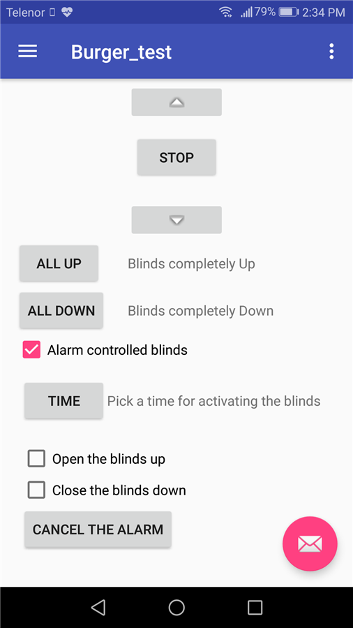
To test out if everything functioned properly instead of trying to go with Android Studio right off I tested everything with MIT App Inventor 2. Added a few buttons and a webviewer and it turned out it worked great. So great in fact that I kept using that app for a long time, until I wanted to get into Android a bit more so then I went and started from scratch. The app is still not finished but for what it is, it function flawlessly for controlling everything. I don't want to continue work on it until I figure out the best way to use 2 way communication between it and the Arduino and until I see what other things I want to add to the system. But I will be keeping this kind of layout for sure, here are some of the pictures of the app itself.
| {gallery} Android App |
|---|
|
Home Screen: Plan for this screen is having it customizable so you can put the things you use most often on here |
|
Burger Menu: As you will notice in some of the images, it's named Burger Test, the reason behind it is was testing the Burger Menu and that's how the side swipe menu is sometimes called, so that name stuck with this version of the app |
|
Lights Section: Most used screen for me by far, this is the screen that controls all of the light functionalities, everything works on it, but the main light relays aren't yet connected to anything so this is primarily for controlling the lamp atm |
|
Blinds Section: This screen is used for controlling the blinds, there are the up down and stop buttons, while I plan on using the all up and all down buttons when I figure out some sensor for the blinds, will probably go with hall effect sensors for it |
|
Blinds Section Alarm: When the checkbox is checked it unlock the other part of the screen which enables us to set up an alarm for the blinds, this is also a work in progress, currently deciding if I want to use the phone to send a signal at the chosen time, or use a RTC module for the Arduino and just send it a time for when to use the blinds |
The code for the app itself can be found here https://github.com/MilosRasic98/Burger_Menu_Test , it's under the MIT license which means anyone is free to do whatever they want with the code, so hopefully it will be helpful to someone! I will be updating the app as I continue forward with it and probably upload it to Google Play once I feel I am finished with it! I am currently at the point with the app where I am working with the alarm but again, still haven't decided on the approach for this part. I am really happy with the layout and the design as it is now, there will be changes of course like a dark theme for the app and generally finishing the rest of the screens that can be seen in the pictures above. That would round up the software for this project as well so it's time to show everything working through some tests!
4. Testing
Here are 3 videos of me showcasing the project. In this first video, I am using an Android Studio Emulator to control the lights (since I film using my phone) and you can see first toggling the light ON/OFF using that method and after that typing in the URL in chrome does the exact same thing. It's a little bit slower over the emulator, but the URL method as well as the real app work incredibly fast and reliably.
In the second video I am using the IR Remote to test out blinds. I mapped the up and down arrows on the remote to move the blinds up and down, and mapped the OK button on the remote to stop them. There are no external limit switches on these blinds so I will have to make some myself for later on, though there are internal ones which shut down the motor when the blinds reach the end.
In the third and last video the main box is shown and how it reacts to the IR Remote. One thing worth pointing out that I had a problem with here, as well as another friend on some other project, these IR receivers can be triggered by many things. The chance of the interference actually being a code from the remote is pretty much zero, but it will completely disable the function of the IR Remote. For example while trying to film this I had to cover up an IR blaster I have on the back of my phone (which it uses with the cameras) because if I didn't do that, the IR receiver won't be able to read any useful data. But when there is no interference it works incredibly fast and reliably. I also love the mechanical sound that the relays are producing when changing their state, so this is one thing that I will for sure try and keep.
5. Long Period Testing
It's one thing testing out once and it works or not and another for testing out for longer periods of time. I'll devote this chapter to the longer testing period and how things were generally with this and what things I had to adapt along the way. As I've said in the beginning I've started with this last year and have been using it non stop pretty much since October/November (if not earlier) with additional small updates every now and then. I set it to a static IP as it can be seen in the code since it's IP got changed after a blackout, something I overlooked when doing everything the first time. For the few months I've been using it, I really didn't have any issues besides that one, I was worried how the Arduino would cope with being turned on for such long periods of time, but I had it on surely for at least a month without powering down and there were no problems with it. I usually turn off everything when I'm leaving for a longer period and every time the system was plug n play, meaning, after powering it up and waiting for 15 seconds or so for it to establish the connection, everything worked without any setup which I love.
6. What's next?
Got a couple of things lined up for this project. Something that I found out recently was that Google Assistant can be configured on the Raspberry Pi which sounds like an interesting addition to the whole thing. Of course there is always continuing the work on the Android app, but for that I want to finish everything else first. I plan on adding more sensors as well, actually already bought some of them for this:
I got a DHT22 temperature and humidity sensor, PIR sensor, Microphone with an amplifier and both digital and analog outputs, as well as a small 7 segment display. The goal of course is showing the current temperature on the phone as well as on the small display, as for the other 2, the PIR sensor would work as an automatic light switch when someone walks in and it's dark in the room, and the idea behind the microphone module is to activate the lights by clapping. Some other things that need to be added as well are stop switches for the blinds, I will probably solve this by attaching a small magnet to the blinds and a couple of hall effect sensors on the side of the window and track the position of the blinds in that way. Some other ideas would maybe be a rain sensor which would close the blinds if it detects rain and open up as soon as it dies down a bit to let the fresh air in as well as an air quality module. But all of these things are a plan in progress for now.
7. Summary
It was a fun project even though I had to work with mains power, which I am not a big fan of, and one that I really use on the day to day bases. My favorite and simplest part would be turning ON and OFF the lights, even though it sounds so simple it really changes a lot so I don't have to climb down and back up every time I want to go to sleep after reading something. This is a project I will for sure invest more time in since I'm getting results that are useful for me down the line while playing around with new sensors. Thanks for reading the blog, hope you liked it!
Milos







Top Comments
-

neilk
-
Cancel
-
Vote Up
+3
Vote Down
-
-
Sign in to reply
-
More
-
Cancel
Comment-

neilk
-
Cancel
-
Vote Up
+3
Vote Down
-
-
Sign in to reply
-
More
-
Cancel
Children