Easy Peasy Oak?
When I saw the post for "Mixing Electronics and Water", I thought to myself "self, this will be a nice easy project to participate in." (I may be paraphrasing a little).
I happened to still have a Digispark Oak sitting around collecting dust, and the last time I used it I recall it was a fairly easy process to connect it up to particle.io and change some values. I could simply add a sensor and have it update to particle.io and maybe use something like IFTTT to make it look good.
Plus I had a project in mind that I actually could really use some monitoring for: I want to keep track of the water level in my pond so that I will get a warning when it needs topping up. (Spoiler alert, I later changed my mind... see title  )
)
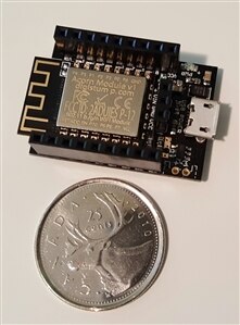
This is the Digistump Oak, with a Canadian quarter for size comparison.
Sadly, however, it turns out my Oak wasn't responding! It's been a few years since I used it last, so it's possible back end changes on Particle.io or maybe changes to my WiFi network caused the issue. I tried several different ways of bringing it back to life, including updating of the firmware, but nothing worked. Sigh.
So that wasted the limited time I had allocated, and I had nothing to show for it.
Dusting Off the ESP-01
But, I still needed that monitoring. And my dusty drawer also included one of the first ESP-01 boards that I bought quite a few years ago. Same chip as the Oak, still programmable using the Arduino IDE, and I've heard it has some pretty good support now. So maybe this was the right time to figure out that little board now.
Plus, the ESP-01 is one of the least expensive WiFi enabled Arduino boards available, at about $2 each, which may come in handy for future projects. Especially projects requiring many remote sensors.
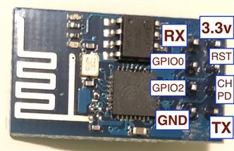
Here is a picture of my ESP-01. I've labelled the pins for future reference.
Programming the ESP-01
The trickiest part of programming the ESP-01 are the physical connections required to hook it up to the Arduino IDE. And even though I saw several examples online, those specific examples didn't seem to work for me.
I ultimately did find some useful diagrams and instructions out there, and with some trial and error and some extra figuring, I finally found a way to connect and program my ESP-01, using a USB-Serial adapter set to 3.3v, and a mess of wires.
The connections I used to program the ESP-01 are as follows:
USB.Serial Adapter - ESP-01
RX - TX
VCC - CH-PD
(ESP-01 RST not connected)
VCC - +3.3v
GND - GND
(ESP-01 GPIO2 not connected)
GND - GPIO0 (sets programming mode)
TX-RX
After flashing, I added the LED to GPIO2. Apparently it can confuse things if it's on while flashing the update.
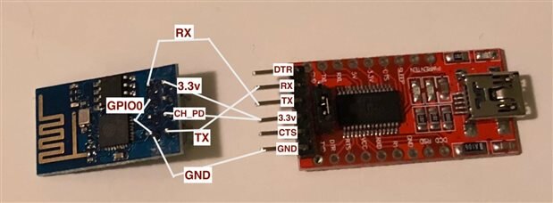
Here is a marked up picture to show the connections I used, partly for my own reference later on, but also I hope it will be helpful to anyone reading this post.
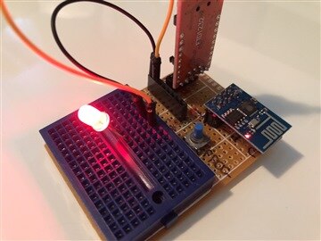
The wiring got a bit complicated, so I decided to solder up the connections onto a perf board to make it easier to disconnect and reconnect it multiple times to facilitate testing.
However, for the first iteration I got things completely backwards - basically I assembled it into mirror image.
One of the reasons I found it a bit hard to keep it all straight in my mind is that the pins on the ESP-01 are on the bottom of the board, and most online example pictures only had the pins marked looking down at the top of the board.
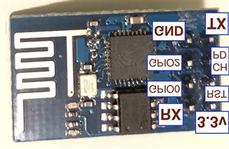
It helped me a little bit to just take a picture of the ESP-01 with marked connections, and then mirror it in software, and work from there, so it matched the underside of the board. I'm not sure if anyone else would find this helpful, or if my brain just works in strange ways sometimes!
Thankfully the second iteration of the perf-board programmer worked perfectly. I also added a switch on the gpio0-gnd connection, to put the board into programming mode at startup, while still allowing it to start into run mode for testing. That works very well, but I really should have added a reset switch as well, as power cycling for each try is a pain.
And then of course I realized that one can just buy an ESP-01 programmer and save all that headache.
But it was a good learning process.
And I did need the programmer right away (eBay can take quite a bit of shipping time).
Blink, Or it Doesn't Count
So now that I finally had the ESP-01 connected up to my Arduino IDE, I was able to make it blink!
As the ESP-01 is very minimal, I had to add my own LED. This board is also very limited for IO, and the only really available GPIO is pin 2. Other pins are useable too, but it can take a fair bit more effort to get them working. This is fine for the purpose I have in mind, but anything requiring more GPIO will benefit from other (and still very low priced) similar ESP8266 board that already have the extra pins connected out.
Side Note:
For those projects requiring extra IO, check out the Witty or WeMos (at about $4 or $5), the Sonoff (about $7), or Adafruit has a Huzzah for a little bit more. I've since ordered one of each of those to give them a try as well. So far I have received the Witty and the Wemos and they are worth the extra $2 just for the plug-and-play programmability and the fact that the 3.3v regulation is handled on the board so that it can be powered simply with a USB phone charger. I was a little disappointed when I later received my Huzzah, as it doesn't have that handy micro-USB power/programming connection.
Here is a picture that compares the sizes. I added a Digispark clone for comparison. The Huzzah arrived later, and is about the same size as the Oak.
Standalone Operation
To actually use the ESP-01 in the field as a remote sensor, I needed to figure out a way to power it up independently. And it would of course need some sort of project case to protect it from rain.
As the ESP-01 runs on 3.3v, I couldn't just use a handy-dandy USB charger like so many other dev boards these days use. So I had to do a little bit of circuit building and soldering. Just enough to keep my skills from getting too rusty and dusty.
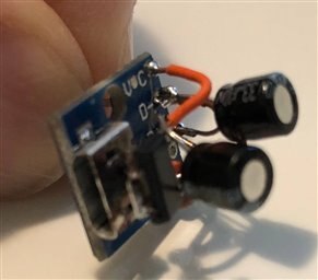
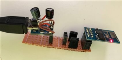
The cool thing is I still had a handful of little micro-USB breakout boards, and I had some AMS1117 3.3v voltage regulators handy. I don't even recall why I bought any of those, but I must have had a good reason for that and it sure came in handy for this project! And by "it" I mean my hoarding tendencies 
It actually turned out quite well, and tiny, although it also wasn't without some trial and error and effort. You won't believe how long it took me to figure out that what should have been one of the easiest solder connections was not properly connected. I think it was the VCC one from the regulator out. I blamed everything else before I figured that out! Sigh.
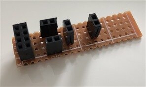
I then decided it would make sense to build a new little breakout board to allow me to easily connect a few things, including the power, to the ESP-01.
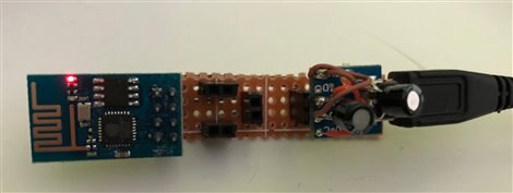
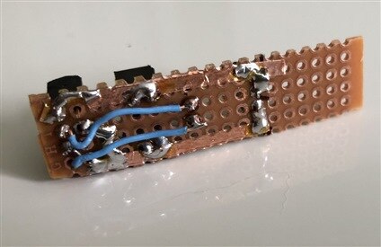
This worked out quite well, and the connections are actually quite basic. The ESP-01 plugs into one side, the 3.3v USB power adapter plugs into the other side, and the headers in the middle provide power and gnd (top and bottom) and access to GPIO2 and GPIO0 (middle).
To help make the connections easier I tried using copper tape in a pcb-style way. This helped a little bit for connecting VCC and GND, but I did still need a few wires to bring it all together.
Connecting To a Server
Now that I knew I could run the ESP-01 standalone, the next step was for it to communicate with a server.
For me I found it simplest to write some php scripts and store them on my own server. There are 3rd party servers that do this kind of thing, but as I've built plenty of PHP scripts in the past I thought I would do this myself to give the most flexibility and freedom. Doing this myself also means I won't have to upgrade any time the provider decides to make changes to their server.
I started off with a very simple script that simply updated a single value in a text file.
Then on the ESP-01 all I had to do was simply make a server call in the format "www.server.com/updatesensor.php?value=1".
Surprisingly, "simply" actually happened this time! The ESP-01 has plenty of examples available for it online, so I was able to take some existing examples and modify them, and with some trial and error was able to get my first successful server update.
Adding a Sensor
Now that I had the ability to update the server, I needed something to update it with. I realized that an on/off switch would be a very limited test and it would be hard to tell when a successful server update had been made, so I hooked up a DS18B20 one-wire temperature sensor instead. As the ESP-01 only has the one easy digital input, that was pretty much the only easy option available.
This worked very well, so I expanded the script to handle multiple sensors, and then I expanded it to store all values for each sensor in a log file rather than just keeping the last update.
At the same time I had been keeping a small viewer style webpage updated to show the information. Once the data logging started I wondered if there was any better way to view the data than just seeing reams of numbers rolling by. As luck might have it, Google has some handy Javascript libraries available that make graphing relatively easy.
The tricky part was getting the data into the right format for it, so I adapted some other samples to build getData.php that provides the graphing software with the data the ESP has been collecting. I went through several online examples to help figure it out, and was able to boil things down to the simpler case that I wanted for my data logger.
So after a bit more late night coding I now have a nice graphical output that takes the live log data and shows an up-to-the-minute graph of it!
(I'll explain what the data means further down in this post)
I've made all of the code available in github, under the MIT licence, for anyone to use freely for any purpose.
The scripts don't have any authentication added, but putting it all in a hidden folder works well enough, I find. And probably the worst that can happen is that someone throws some bad data your way. I won't be publishing my folder names publicly, as I'd rather not deal with the annoyance of random hacker types, but for any fellow element14'ers I can easily set up a folder for use.
Using the Scripts
Updating the server with a new value is simple. You can try it from the command line in this form: (Note: this link purposely does not point to a proper folder - it just shows how to use the script)
The server then stores that data into sensorValues.json in JSON format, with a timestamp indicating when it was last updated:
{"3":{"value":"25.5","timestamp":"2018-04-04 07:02:43pm"}}
Each sensor ID ("3" in this case) gets a similar entry.
At the same time, the script will add the new data to the end of a log file for that sensor. The log files are in .csv format, which makes them easy to convert into input data for the graph library later, but also allows it to be easily imported into spreadsheet software like OpenOffice or MS Excel.
I also added a tiny bit of security in case of a breach, to limit the number of sensors for which log files are created. For this reason, the only sensors which get a log file are 001 through 009.
The filename for each sensor is in the format log_003.csv
You can then view the graph by loading the webpage: (Note: this link does work! but that folder does not contain the update scripts)
http://mulberryland.com/secretsensorfolder/sensorgraph.html
At this point I only show the graph for sensor 001. The code in getData.php can be updated to graph a different log file, but ultimately I'll likely update the graph html file and getData.php file to allow specification of a sensor. As I only have one sensor at the moment, this wasn't a high priority.
Keeping Things Dry
The next step is to put the sensor where I want to take the measurements. So I need to make sure it stays safe and dry.
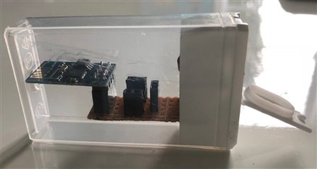
I wasn't super happy with the look of my breakout board, even though it worked well enough, so I decided it was time to hide it inside of some case that would also keep things safe from rain.
As it turns out, I found a tic-tac case that fit the whole setup perfectly. It's clear though, so this also meant embracing the ruggedness of my messy perf board. On the bright side though, it does show off the nerdy side of the sensor and gives visibility of the little blinky lights (the ESP-01 does have power and tx/rx LEDs, very pretty at night). And, as I later learned, it was nice to see through the case to notice loose connections later, heh.
Logging Some REAL Data
This is what we came for!
Well, not completely exactly what I came for - I originally wanted to keep an eye on my pond water level, but two things made me go a different route: 1, it's winter and the rain keeps the pond topped up continuously; and 2, I have a temperature sensor already hooked up and giving nice variable data for testing.
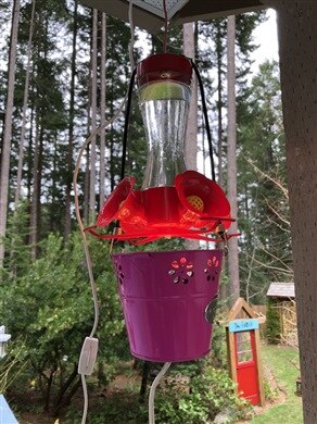
So another application came to mind: my hummingbird feeder!
We have hummingbirds that overwinter here, so they depend on the feeders being available through the winter. The problem is that when the weather gets really cold the feeders can freeze up.
One solution locals often use is to hang a light bulb underneath it. I started out with some very big and ugly tin cans with highish wattage light bulbs under them, but refined it to use a smaller neater setup later, with a smaller lightbulb like the ones used in salt lamps.
I wanted to see how well this smaller light method works to keep my hummingbird feeder from freezing.
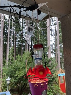
I already had an extension cord close to the hummingbird feeder for that lightbulb, so I simply plugged a small cube-style phone charger in, and plugged in my standalone ESP-01.
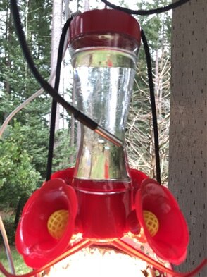
I then placed the temperature sensor up against the glass, and covered it with a little bit of insulation, all held in place with an elastic band. The reason for the insulation is that I want the water/glass temperature and not the outside temperature.
This worked wonderfully!
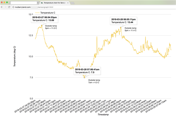
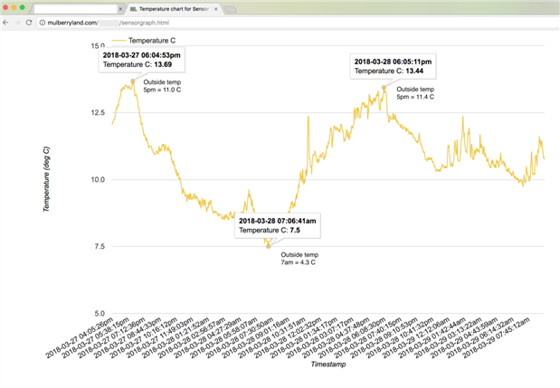
Check out the resulting graph. I added notes to indicate what the outdoor temperature was (based on Environment Canada data).
The good news is that the light bulb does keep the feeder about 3 degrees above the outside temperature, which is usually enough to keep the feeder from freezing. This was for a 15 watt light bulb, so I could always upgrade to a 25 watt bulb if needed, and maybe insulate the bottle when things get really cold.
The Results
I'm very happily surprised how well this project turned out for me, and how useful it actually ended up being. I'll likely be doing more temperature logging of this sort for other purposes later - like keeping track of my holiday trailer interior temperatures (summer and winter both), maybe checking up on pond water conditions, and who knows what else.
In addition to temperature logging, it would also not take a lot of changes to record anything else required.
I was also very happily surprised about the capability of the ESP8266-based boards that are available out there and at very affordable price points. These handy little boards open up a lot of possibilities for WiFi enabled projects.
I hope this is also something that will be useful to others out there, which is why I'm sharing all the pieces here.
Future Enhancements?
I already mentioned that I would like to update the server side graph to allow showing a graph of more than just the 001 sensor.
But I also have some sensor upgrades in mind - given that the one-wire setup allows multiple sensors connected to the one IO pin, the first thing I'd like to add is an outdoor temperature sensor to simultaneously record inside and outside temperature - particularly useful for that hummingbird feeder, for example (I was using Environment Canada data as an estimate before).
I would also like to hook it up to a small lithium battery and a solar cell - by making the ESP chip sleep most of the time, with maybe hourly updates, this might be just enough power to keep things going. The trickiest part for that might be to ensure that the battery does not get drained too low and also that the chip does not receive power unless there is enough battery power available to complete at least a few cycles. I've also thought about using a super capacitor for this purpose but I think that might be a stretch given that their capacity is that much lower - however, that might work well enough in a situation where we are controlling a greenhouse and only need it to be operational during daylight hours.
Source Code and Summary of Files
I've added all of the source code to my GitHub repository: https://github.com/ntewinkel/electronics/tree/master/ESP-01
Firmware for the ESP-01, for the Arduino IDE: ESP_temp_sensor.ino
Testing firmware for the ESP-01, for the Arduino IDE: ESP_sensor_test.ino which simply loops through, sending values to the server.
I've included a text summary of the connections required to program it: "ESP-01 connections.rtf"
The ESP-01 calls this script on the server: updateSensorValue.php
That script stores the values, with timestamps, into a file on the server named sensorValues.json (included as an example, but is created by the server)
That same script also logs a history of values+timestamps in a separate log file, named log_001.csv (where 001 is the sensor name). This script restricts logging to sensors named "000" through "009" to avoid abuse, as each creates a new file. I've included log_001.csv as an example. It's in proper .csv format so you can easily open/view it with spreadsheet software like OpenOffice Calc.
I've also included a no-logging version of that script: updateSensorValue_no_logging.php. As I build and test things, I usually start with a basic starting point and then add features as things progress.
The sensorsSummary.php script shows a basic summary of the sensor values in an html table. You can view it from a browser, just like any other webpage.
And this is the HTML page that shows a graph for a sensor: sensorgraph.html
That html page calls a helper script named getData.php that translates the stored data from log_001.csv into a format used by the Google functions to create the graph. Note that log_001.csv is currently hardcoded. I want to one day update the script to handle multiple log files, to allow sensorgraph.html to be called with a parameter that is the sensor name.
Video!
Here is a video to show the general workings of the data logging setup, along with some extra angles and messy wires 
Enjoy!
-Nico


Top Comments
-

james.flynn
-
Cancel
-
Vote Up
+5
Vote Down
-
-
Sign in to reply
-
More
-
Cancel
-

ntewinkel
in reply to james.flynn
-
Cancel
-
Vote Up
+1
Vote Down
-
-
Sign in to reply
-
More
-
Cancel
Comment-

ntewinkel
in reply to james.flynn
-
Cancel
-
Vote Up
+1
Vote Down
-
-
Sign in to reply
-
More
-
Cancel
Children