element14 Community
element14 Community
    Register Log In
  • Site
  • Search
  • Log In Register
  • Community Hub
    Community Hub
    • What's New on element14
    • Feedback and Support
    • Benefits of Membership
    • Personal Blogs
    • Members Area
    • Achievement Levels
  • Learn
    Learn
    • Ask an Expert
    • eBooks
    • element14 presents
    • Learning Center
    • Tech Spotlight
    • STEM Academy
    • Webinars, Training and Events
    • Learning Groups
  • Technologies
    Technologies
    • 3D Printing
    • FPGA
    • Industrial Automation
    • Internet of Things
    • Power & Energy
    • Sensors
    • Technology Groups
  • Challenges & Projects
    Challenges & Projects
    • Design Challenges
    • element14 presents Projects
    • Project14
    • Arduino Projects
    • Raspberry Pi Projects
    • Project Groups
  • Products
    Products
    • Arduino
    • Avnet Boards Community
    • Dev Tools
    • Manufacturers
    • Multicomp Pro
    • Product Groups
    • Raspberry Pi
    • RoadTests & Reviews
  • Store
    Store
    • Visit Your Store
    • Choose another store...
      • Europe
      •  Austria (German)
      •  Belgium (Dutch, French)
      •  Bulgaria (Bulgarian)
      •  Czech Republic (Czech)
      •  Denmark (Danish)
      •  Estonia (Estonian)
      •  Finland (Finnish)
      •  France (French)
      •  Germany (German)
      •  Hungary (Hungarian)
      •  Ireland
      •  Israel
      •  Italy (Italian)
      •  Latvia (Latvian)
      •  
      •  Lithuania (Lithuanian)
      •  Netherlands (Dutch)
      •  Norway (Norwegian)
      •  Poland (Polish)
      •  Portugal (Portuguese)
      •  Romania (Romanian)
      •  Russia (Russian)
      •  Slovakia (Slovak)
      •  Slovenia (Slovenian)
      •  Spain (Spanish)
      •  Sweden (Swedish)
      •  Switzerland(German, French)
      •  Turkey (Turkish)
      •  United Kingdom
      • Asia Pacific
      •  Australia
      •  China
      •  Hong Kong
      •  India
      •  Korea (Korean)
      •  Malaysia
      •  New Zealand
      •  Philippines
      •  Singapore
      •  Taiwan
      •  Thailand (Thai)
      • Americas
      •  Brazil (Portuguese)
      •  Canada
      •  Mexico (Spanish)
      •  United States
      Can't find the country/region you're looking for? Visit our export site or find a local distributor.
  • Translate
  • Profile
  • Settings
Month of Robots
  • Challenges & Projects
  • Project14
  • Month of Robots
  • More
  • Cancel
Month of Robots
Blog NVIDIA Jetson Nano: JetBot Assemble
  • Blog
  • Forum
  • Documents
  • Events
  • Polls
  • Files
  • Members
  • Mentions
  • Sub-Groups
  • Tags
  • More
  • Cancel
  • New
Month of Robots requires membership for participation - click to join
  • Share
  • More
  • Cancel
Group Actions
  • Group RSS
  • More
  • Cancel
Engagement
  • Author Author: jomoenginer
  • Date Created: 28 Apr 2019 10:05 AM Date Created
  • Views 3471 views
  • Likes 17 likes
  • Comments 14 comments
  • nvidia jetson nano
  • robotics
  • jetbot
  • robot
  • morobotsch
  • raspberry pi
  • robot project
  • computer vision
Related
Recommended

NVIDIA Jetson Nano: JetBot Assemble

jomoenginer
jomoenginer
28 Apr 2019

Overview


In a previous post, and introduction to the NVIDIA Jetson Nano JetBot was given showing the parts required to create the JetBot as per the NVIDIA specs.  In this post, these parts will be used to assemble the JetBot and a basic Motion test will be shown.


image


Previous Related Posts

NVIDIA Jetson Nano

NVIDIA Jetson Nano: JetBot Intro

NVIDIA Jetson Nano: Collision Avoidance


Hardware Setup


The Hardware Setup required and tools need to assmble the JetBot are listed on the NVIDIA-AI-IOT JetBot WiKi

https://github.com/NVIDIA-AI-IOT/jetbot/wiki/Hardware-Setup


Hardware Required

Part Detail Quantity
M2 Screw 8mm long, self tapping 20
M3 Screw 25mm long 4
M3 Nut 4
Jumper wires Female-Female 4


It is suggested to use the M2 Screws listed since the other option is to use #2 standard screws but these do not work as well as the M2.  The M3 can be replaced by 4-40 x 1" screws though.


WiFi Module Install

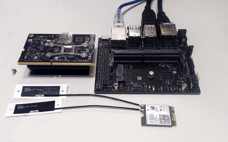
To install the M.2 Intel Dual Band Wireless-Ac 8265 W/Bt8mm long, self tapping, the Jetson Nano SoM must be removed from the Carrier board.   This requires removing the 2 mounting screws and releasing the latches on the side of the M.2 socket. There is a screw in the center of the board that needs to be removed which holds the WiFi module in place. Also, the 2 Antennas must be attached at this stage.

image


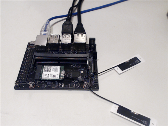
Once the Antennas are installed, gentle insert the WiFi module into the M.2 slot on the carrier board and place the WiFi module screw back in place.


image


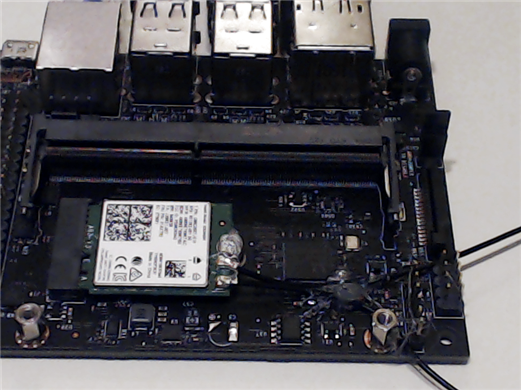
NOTE: Hot Glue was used to hold down the wires and on the mounting screw.

image


Place the Jetson Nano SoM back into the slot on the Carrier board and screw it back down.


PiOLED

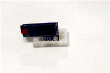
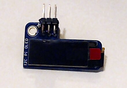
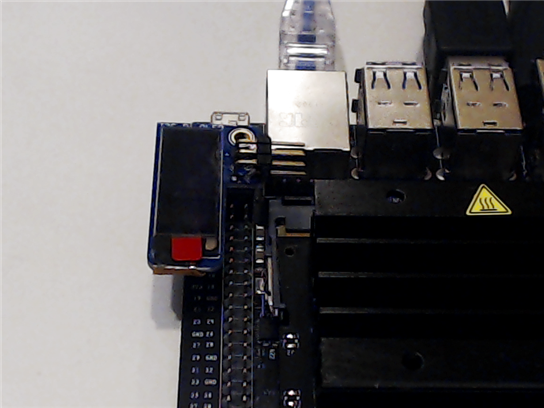
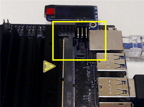
To view the assigned IP Address of the board when it first boots, a PiOLED is attached to Pins 1-6 of the J41 Header.  These pins supply the 3.3 v, Ground and SDL and SCL i2C signals for both the PiOLED and the Motor Board. To attached the Motor Board to these signals, a 6 pin right angle head is added to the PiOLED Display.  A word of caution, the PiOLED is a bit fragile so care must be taken when soldering the pins of the right angle header to the PiOLED head pins.  The first attempt here results in a dead PiOLED.   Also, for the second attempt, jumper wires were used instead of a right angle header since the wires from the Motor board block the header for the Heat Sink Fan.


PiOLED before right angle header attached.

image


PiOLED after Header attached

image


PiOLED Mounted to J41 of Jetson Nano

image


NOTE: This image shows the Heat Sink Fan header being block by the right angle header on the PiOLED

image


NOTE: If the PiOLED is not connected when booting the JetBot with the JetBot image, the following message will continue to appear in the 'dmesg' output.

Address 0x3c is for the PiOLED


tegra-i2c 7000c400.i2c: no acknowledge from address 0x3c


Motor Driver

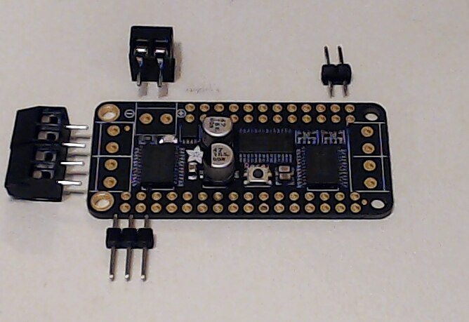
The Motor Driver is shipped without the headers and screw terminals attached, so these need to be soldered by the individual.

image


The 3 pin header is for the 3.3v and Ground connection for controlling the Motor Driver, the Upper Screw Terminal is used for the Motors via the USB Power Bank.

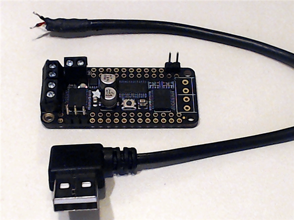
The 2 pin header is for the SDA and SCL i2c signals and the 2 Screw terminals to the left are for the motor connections.  Note the orientation of the connections.


image


NOTE: The 2 Type A to Micro, right angle USB cables listed in the BOM are not identical.  The Micro USB Connections are mirror opposites so care must be taken to cut the correct one to attach to the Motor Board otherwise the Power connection to the Nano will interfere with the Ethernet port.

Here the Micro USB connection was removed and the Green and White wires were cut back as well as the shielding.  The Red and Black Wires were stripped back so they can be attached to the Motor Board.


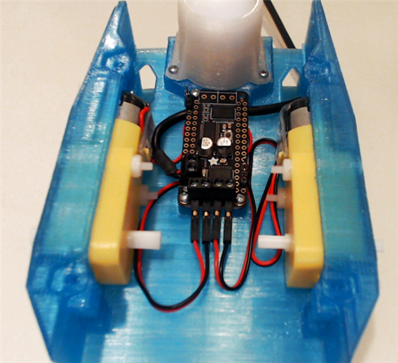
Mount the Motor Board using 4 M2 self tapping screws and DC Motors to the 3D printed chassis with 4 M3 screws and nuts .   The modified USB cable is connected to the Screw terminal on the Motor Board and route the cable under the Moot Board and out the side of the chassis.  Attach the Motor wires to the Motor Board.


image


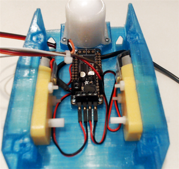
Connect the 4 Jumper wires to the Motor Board as such:

  • Red       - 3.3v
  • Brown   - Ground
  • Orange - SDA
  • Yellow   - SCL  (White was used in place of Yellow)


image


Camera Module


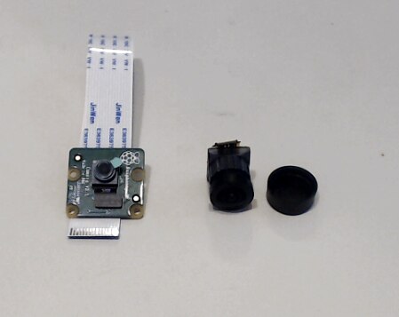
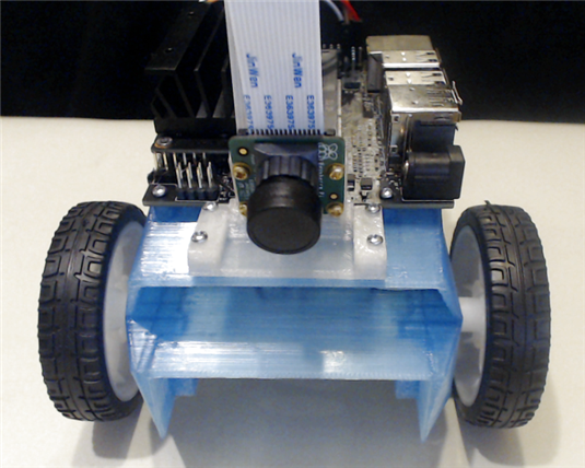
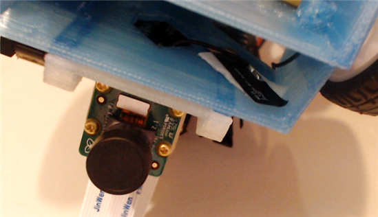
To enhance the filed of view of the camera, a Wide Angle Lens module is used to replace the Raspberry Pi Camera v2 Module.

image


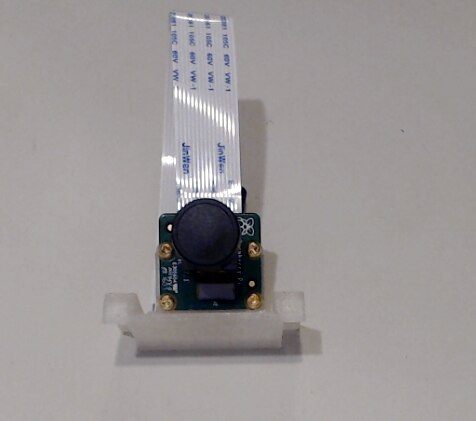
The Raspberry Pi Camera module can be pealed off and disconnected from the Camera board and the Wide angle module placed and connected in its place.  This can be performed before or after the Camera board is attached to the 3D printed Camera Mount.


image


Final Assembly


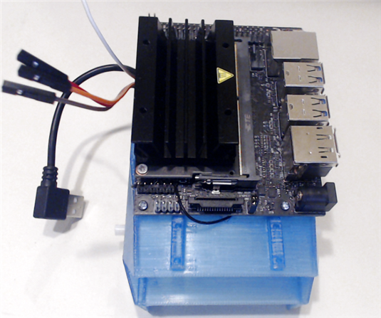
Attached the NVIDIA Jetson Nano to the Chassis using 4 M2 screws.

image


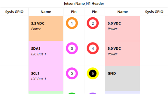
Attache the Wheels and the Camera Mount on the chassis, and connect the Motor Driver wires to J41 of the Jetson Nano.image
 

Wire connections

  • Red       - 3.3v
  • Brown   - GND
  • Orange - SDA
  • Yellow   - SCL  (White was used in place of Yellow)

Image from:

https://www.jetsonhacks.com/nvidia-jetson-nano-j41-header-pinout/


image

Camera Mount

image


Peal the paper from the adhesive Antenna Film and attach one to the underside of the top part of the chassis and the other to the lower part.

Note: It is best to ensure these are as close to the side of the chassis as possible so as to not interfere with the Power Bank placement.


Lower attachment

image


Upper attachment

image


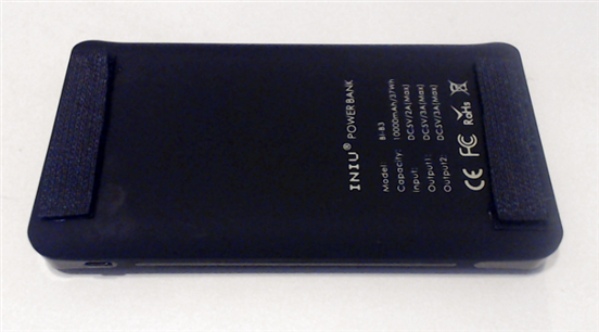
Remove the Power Bank from its protective sleeve and either place double sided adhesive or, in this case, Velcro to the Power Bank so it will hold in place in the chassis..

image


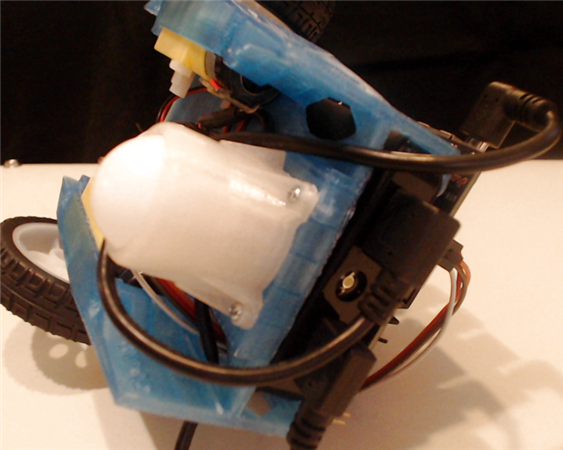
Slip the Power Bank into the chassis ensuring the 2 USB connections are on the end that aligns with the P41 header of the Jetson Nano. Route the Jetson Nano cable around the Caster Base under the chassis.

image


The connections to the Power Bank should like like the following

image


NOTE: Since the PiOLED was killed in the header placement, thus it is not attached at this time.


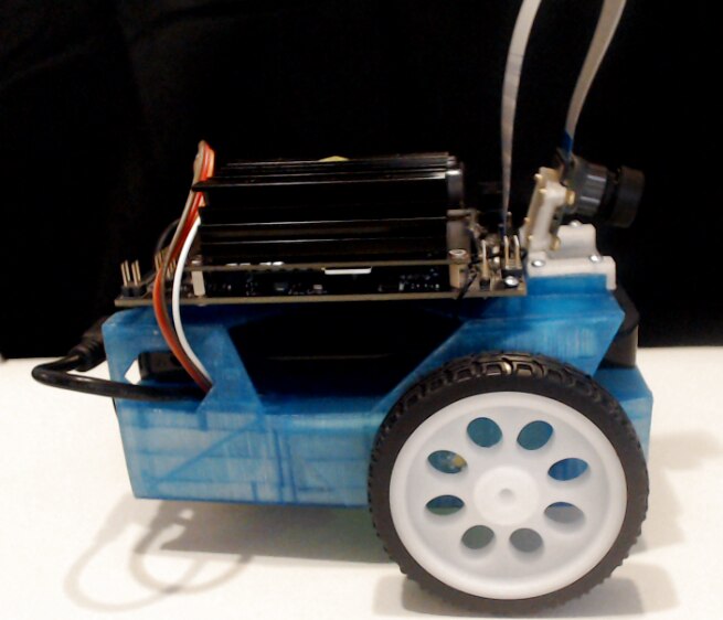
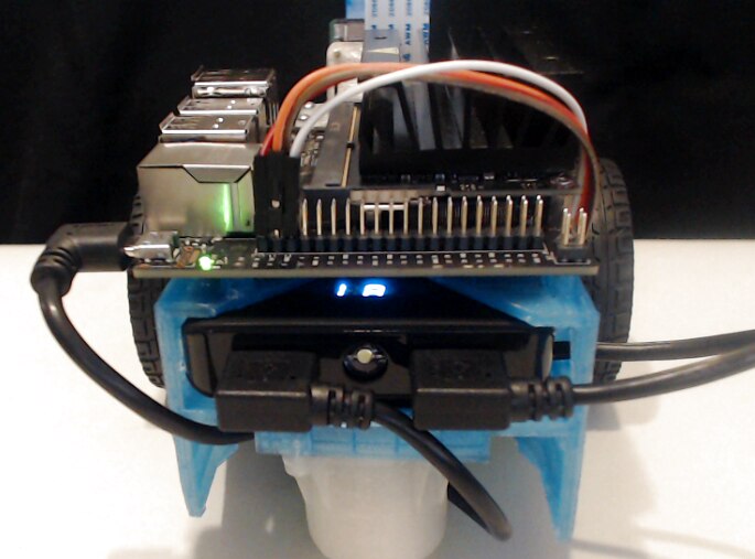
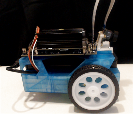
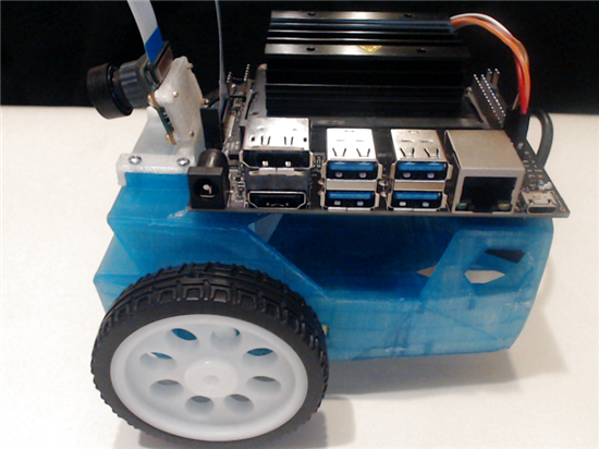
The End result of the JetBot assemble in this instance is as follows.

image


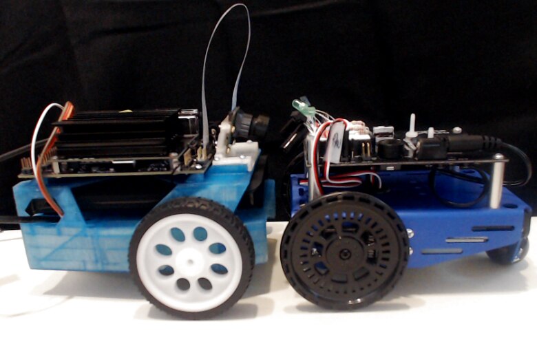
Face to face with a Parallax cyber:bot with Shield Bot Chassis, the JetBot is quite similar in size to the Parallax Bot.

Interesting, the NVIDIA Jetson Nano JetBot came in at around $250 US and the Parallax Shield Bot with cyber:bot Board, micro:bit board and rechargeable batteries was around  $241 US (or $200 as a complete kit without batteries). However, in the case of the Parallax Bot, the Chassis is provided where the JetBot must be 3d printed or completed by a 3D printing service.


image


JetBot Example Video

In the following Video, the Assembled JetBot is shown as well as a walk through of the Basic Motion Jupyter Notebook that is hosted on the JetBot.  This example shows how to control the JetBot from Python.


You don't have permission to edit metadata of this video.
Edit media
x
image
Upload Preview
image

  • Sign in to reply

Top Comments

  • kiri-ll
    kiri-ll over 6 years ago +4
    The machine looks great! I always wanted to see how the training of AI looks like, so I am very curious how this your project will go!
  • jomoenginer
    jomoenginer over 6 years ago in reply to 14rhb +4
    Rod, Thanks. The 3D printer I have is a xyz da Vinci Mini (The orange one) which I picked up for less than $200.00 US. There is an updated one now but I am not sure how well that one performs. The one…
  • 14rhb
    14rhb over 6 years ago +3
    Hi Jon, This is a very well presented build blog which I am really enjoying reading, thank you for taking the time to photograph and write up all the steps. Your 3D printed parts are also very professional…
Parents
  • dubbie
    dubbie over 6 years ago

    A good build. I wish I could print the chassis.


    Dubbie

    • Cancel
    • Vote Up +3 Vote Down
    • Sign in to reply
    • More
    • Cancel
Comment
  • dubbie
    dubbie over 6 years ago

    A good build. I wish I could print the chassis.


    Dubbie

    • Cancel
    • Vote Up +3 Vote Down
    • Sign in to reply
    • More
    • Cancel
Children
  • jomoenginer
    jomoenginer over 6 years ago in reply to dubbie

    I am not sure where you are located, but you might want to look in your locale to see if there are any Maker Groups or Labs or even a local college or public library that may have 3D Printers you could use.


    There is a 3D printing page in the JetBot WiKi where they list possible sources to have the chassis and such 3D printed for you.  There is a cost though.

    https://github.com/NVIDIA-AI-IOT/jetbot/wiki/3d-printing

    • Cancel
    • Vote Up +3 Vote Down
    • Sign in to reply
    • More
    • Cancel
  • dubbie
    dubbie over 6 years ago in reply to jomoenginer

    Jon,


    There is always a cost involved. However, I think the best solution would be a bigger 3D printer although I'm not sure my wife agrees! What I might try sometime when I actually have some spare time, is to try and design my own chassis using TinkerCAD that fits into my 3D printer, either as a single smaller part of two or more parts that fix together. I want to get better at designing in TinkerCAD as at present my designs are very boxy - which is the inherent nature of TinkerCAD.


    Dubbie

    • Cancel
    • Vote Up +3 Vote Down
    • Sign in to reply
    • More
    • Cancel
  • 14rhb
    14rhb over 6 years ago in reply to dubbie

    Or use your existing printer to make a larger one for such oversized projects? See RepRap


    Rod

    • Cancel
    • Vote Up +3 Vote Down
    • Sign in to reply
    • More
    • Cancel
  • dubbie
    dubbie over 6 years ago in reply to 14rhb

    Rod,


    When I was thinking of getting my first 3D printer I did look into the RepRap approach, but then decided life was too short to spend it all on making something I could buy. I have seen other 3D printers with much larger printing areas and wondered if they had as much trouble as I did with my small prints.


    Dubbie

    • Cancel
    • Vote Up +2 Vote Down
    • Sign in to reply
    • More
    • Cancel
  • 14rhb
    14rhb over 6 years ago in reply to dubbie

    ...but then decided life was too short to spend it all on making something I could buy.

    My attempt to make something along the approach of a RepRap Prusa i3 sat on the worktop for over 2 years and probably never got over 20% complete, so I see your point.


    Rod

    • Cancel
    • Vote Up +3 Vote Down
    • Sign in to reply
    • More
    • Cancel
element14 Community

element14 is the first online community specifically for engineers. Connect with your peers and get expert answers to your questions.

  • Members
  • Learn
  • Technologies
  • Challenges & Projects
  • Products
  • Store
  • About Us
  • Feedback & Support
  • FAQs
  • Terms of Use
  • Privacy Policy
  • Legal and Copyright Notices
  • Sitemap
  • Cookies

An Avnet Company © 2025 Premier Farnell Limited. All Rights Reserved.

Premier Farnell Ltd, registered in England and Wales (no 00876412), registered office: Farnell House, Forge Lane, Leeds LS12 2NE.

ICP 备案号 10220084.

Follow element14

  • X
  • Facebook
  • linkedin
  • YouTube