In my prior blog ( Multi-Voice Synthesizer - Part 3 - Main Board rework and Echo Module bring-up. ) I covered my bring up of the Main Board and Echo Module. Having finally made each of the circuits function according to plan, I have redesigned the boards for this project. I just ordered new PCBs today, so I thought I would share the designs and discuss the changes.
Voice Module
The Voice Module board saw the largest amount of design changes. Here is a list of the updates to this board:
- Added an optional Crystal Oscillator to prevent the current temperature variable main clock and the resulting waveforms for the Voice Module. With this design I can either used the internal R/C oscillator or a Crystal Oscillator to supply the ATtiny1614 with the 20 Mhz main clock.
- Added a more conventional Voltage Controlled Amplifier (VCA) to control the Attack, Sustain, Decay and Release (ADSR) amplitude changes. This circuit will used a processor generated PWM signal, filtered and buffered, to control the constant current source of the VCA. The processor will use an 8-bit Timer, with a 10MHz clock to generate a variable duty cycle 25.6µS clock (625kHz) to control the amplifier.
- Corrected the State-Variable active filter circuit. In the initial design I accidentally swapped the +/- inputs on the Op-Amps, which did not work too well. After breadboarding the circuit, I was able to prove that the filter work quite well.
- Added an onboard 2.5V bias circuit to use instead of using a single regulator on the main board and bussing the voltage to each of the Voice Modules.
- Modified the edge connections with the Main board (6 pins instead of the prior 8 pins).
- Miscellaneous schematic errors fixed. The most glaring error was leaving the N/C pin on the MAX5387 (dual digital potentiometer) open. There was an obscure note in the specification that this pin should be grounded.
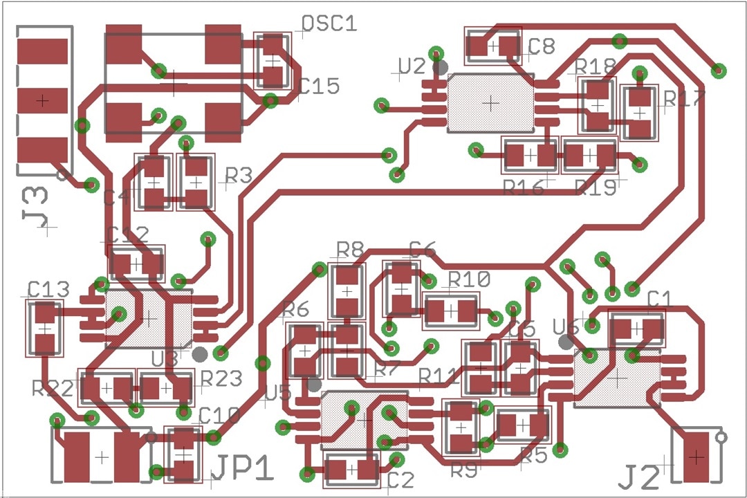
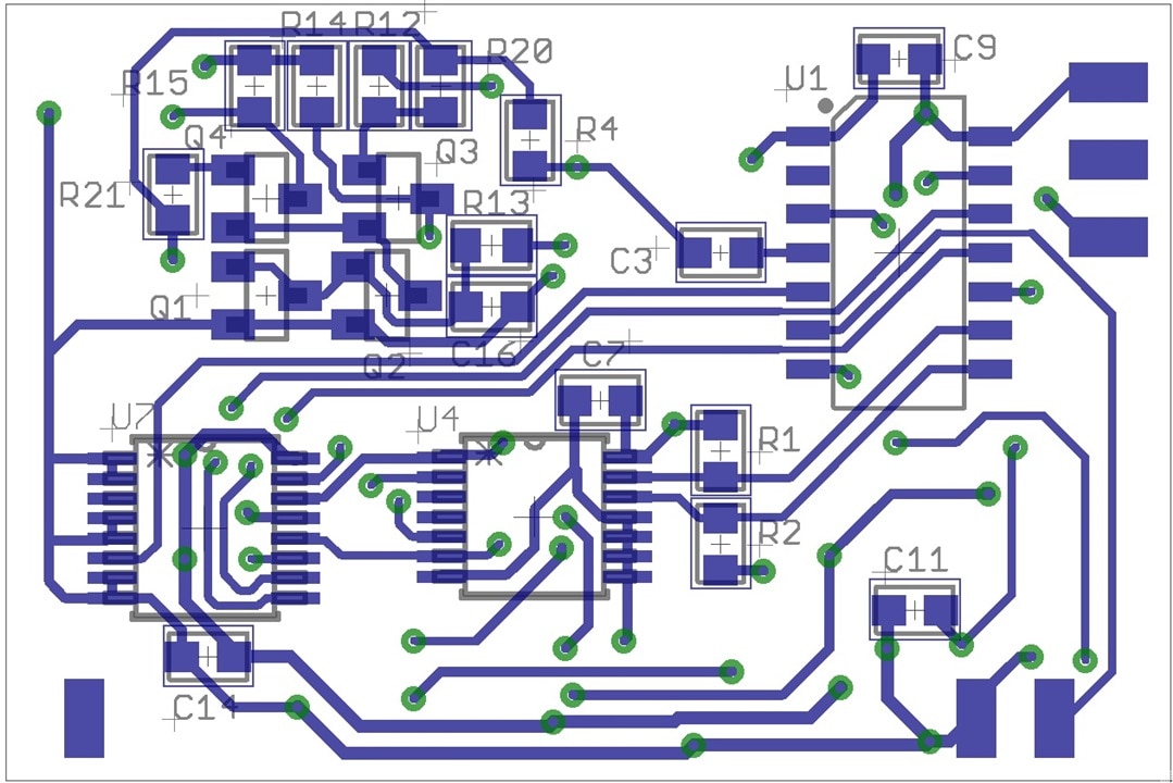
The added circuitry on the Voice Module made the layout a bit tighter, but I was able to fit it all into the targeted 1.0" by 1.5" PCB side. Here is the new schematic:
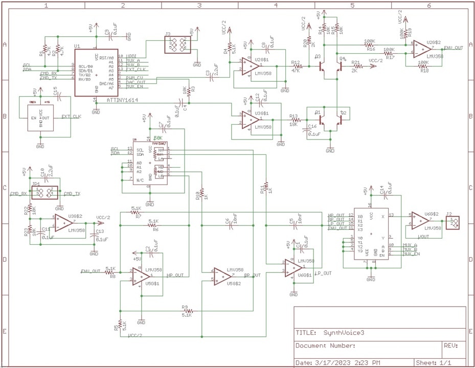
Here are the front and back layouts:
Main Board
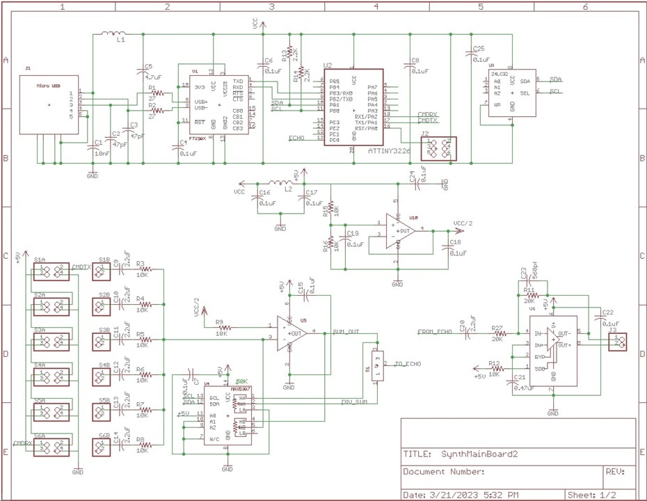
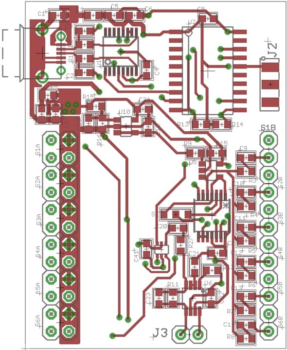
On the Main Board there were also quite a few changes, Here is a list of the updates to the board:
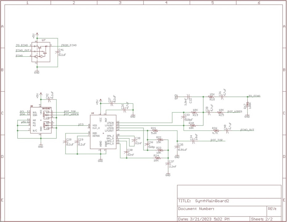
- Move the Echo Module circuitry onto the Main Board. I was hopeful that I could reduce the number of PCBs in the project and remove some connectors, and that has been accomplished.
- Added a serial EEPROM to hold waveform tables and MIDI files. The waveforms can be loaded under MIDI variables to each Voice Module as a part of the setup instructions. This will allow a large number of waveshapes to be saved on in the EEPROM. This will also simplify the Voice Module coding, especially the interrupt function generating the waveforms.
- Removed the old regulator for the 2.5V bias signal and replaced in with a simple divider and buffer circuit. this bias voltage will only be used for local circuits.
- Added a volume control to the output of the Mixer/Summing circuit (so I don't disturb my wife while I am testing, some of the higher frequency notes can be a little annoying).
- Modified the connectors for the Voice Module slots. Eliminating 2 pins from each of the six slots (0.1" spacing) freed up a bit of space making it easier to place all of the Echo Module circuitry onto the Main Board (that and the 8 pins of the old connector to support the external Echo processor).
- Miscellaneous schematic errors fixed. The most glaring error was leaving the N/C pin on the MAX5387 (dual digital potentiometer) open. There was an obscure note in the specification that this pin should be grounded.
Here is the updated schematic for the Main Board (now two pages):
Here are the updated layouts for the Main Board:
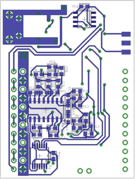
Echo Module
This was folded into the Main Board. Initially, I was concerned if if would fit onto the Main Board and also concerned if the design would work well in this application, but the Echo Module was just about the only only part of the initial design that worked right from the start. I still might need to tune and tweak some components, but I was still pretty happy with the results.
New PCBs will be ready in about a week. In the mean time I will attempt to work on the software, with the hope of having some usable software in place as the boards are assembled.
Thanks for reading along.
