


Introduction
This is a project I have been planning for a while. I want to know if my caravan is moving (when it shouldn't be!) and also to know where it is any time. I purchased an mkr gsm1400 some time ago and all I have done so far is check it worked by loading the blink script. So I thought it was time to put it to use.
Project plan
I want to use the gsm1400 together with a neo-6m to get gps position and send location based text messages. I want to locate it in my caravan so I need to make a case for everything to fit in.
Project Steps
connect everything up
write a script
test it works
test the power consumption
make a case
locate in caravan
test it still works.
Parts list
Arduino GSM MKR1400
GY-GPS6MV2 board
usb cable to connect to pc
1500Mah Lipo battery
SIM card
8 screws
piece of ribbon for battery holder
Parts added as afterthoughts
Perf board 90mm x 70mm
female headers
Oled display
RGB LED
Software required
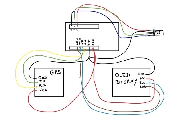
Connecting everything up
First insert the Sim Card.
Then connect the GPS. The GPS I am using has 4 pins VCC, GND, TX and RX.
Here is the connection diagram.
Script plan
So with everything connected up I want to write the script. The script needs to perform the following functions:
- Gsm1400 to initialise
- get gps location.
- store this location as the home position
- send location to pre planned mobile phone
- wait for a response from phone
- check correct phone was used
- react to responses the planned responses are;
STORE tells gsm1400 to monitor current position and report changes
HALT tells gsm1400 to stop monitoring because I’m towing the caravan.
TEST tells gsm1400 to send current location
- if gps position changes send location to planned phone
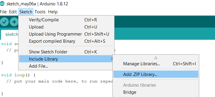
Loading Libraries
Before you can write the script you need to load the necessary libraries. I opted for the TinyGPSplus library which can be found on github here.
https://github.com/mikalhart/TinyGPSPlus
Download the zip file.
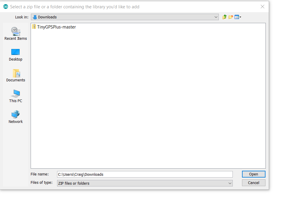
Then in Arduino IDE Sketch > Include Library > Add ZIP Library
Find your download and click open
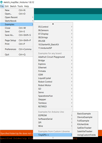
The library will be installed and you can check this by looking at the examples under the File menu
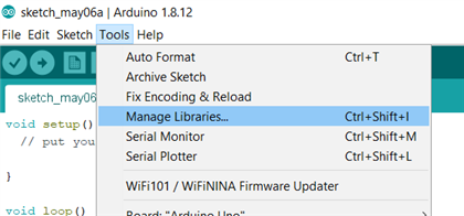
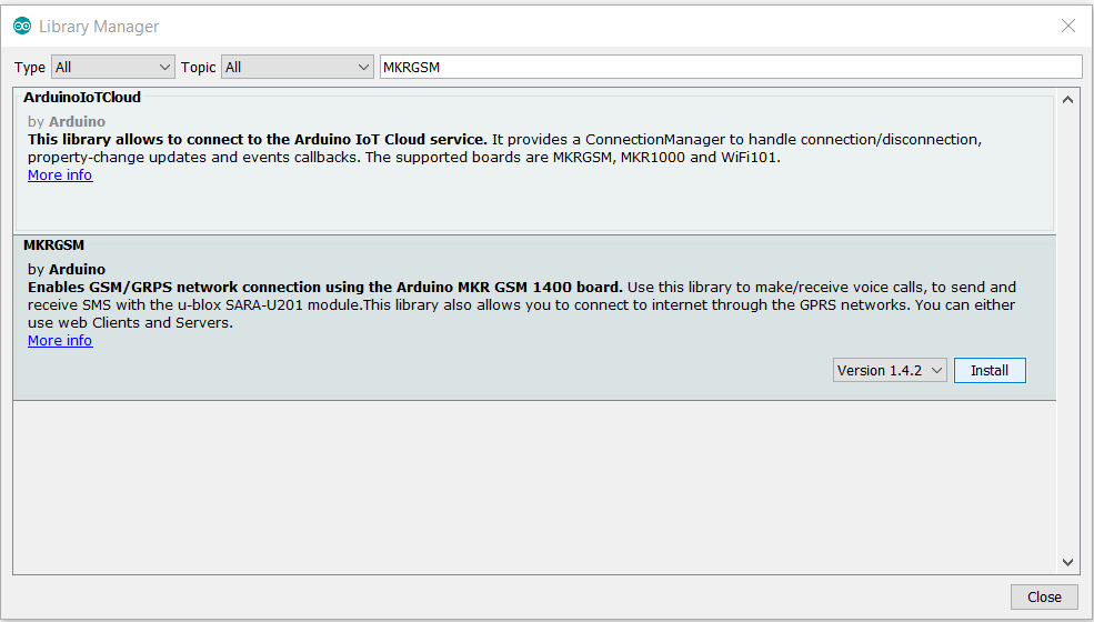
Next you need to install the GSM1400 libraries and this can be found under Tools>Manage Libraries..
Search for MKRGSM and click on install.
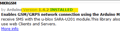
When it is finished the version number and INSTALLED will appear alongside the author.
The script
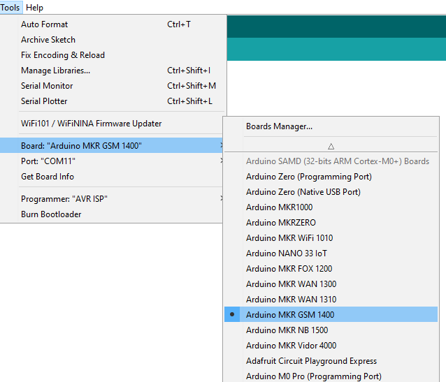
With the libraries installed select the board -
We now also have the sample sketches for MKR1400 available. I opened up and tested the sketches ReceiveSMS and SendSMS and they worked really well.

I also tested the TinyGPSplus BasicExample and this also worked well.
I stripped down the three samples and this formed the basis of my sketch which I have annotated as best I can. In some places I am aware the coding could be improved and I would appreciate any pointers to this end. I noticed that the latitude and longitude coordinates constantly fluctuate and I did some analysis of the values. I found that the values constantly change even if the gps isn't moving. So just storing the latitude and longitude then checking again later for a match wouldn't work. So I decided to store the latitude and longitude but only alert if either the latitude and longitude position changed by more than .0003.
So the sketch will start the gsm then from the gps. It will get and store the current position and send a text message containing the stored location. It will then monitor the gps position and if it has changed, as discussed above, then it it will send a text message every 2 minutes with the latest gps position. The script is also monitoring the sms feed and is waiting to receive one of 3 messages; Store, Halt or Test. Texting Halt to the GSM phone number will pause monitoring of the gps location and would be used when you want to move the caravan. Texting Store will take the current gps location and change it the stored location and gps monitoring will continue. A text message containing Test will get Cara-duino to send the current position. Once the status is Moving a Halt message must be sent before sending Store again.
Here's the code ... there are lots of Serial.print lines which are only there for error proofing. Now that I am happy it is working I could remove these lines.
#include <TinyGPS++.h>  // GPS library
#include <MKRGSM.h>     //GSM libary
#include <ArduinoLowPower.h>
#include <Adafruit_SSD1306.h> //Oled display library
#include <Wire.h>             //I2C library
// The TinyGPS++ object
TinyGPSPlus gps;    //Create a GPS object
Adafruit_SSD1306 display(4);
// initialize the GSM library instance
GSM gsmAccess;
GSM_SMS sms;
//variables to control text message responses
//bool responded = true; //should be initialised to false set to true to avoid unnecessary sms
bool msgreceived = false; //not currently used
char admin_phone[14] = {'+', '4', '4', '1', '2', '3', '4', '5', '6', '7', '8', '9', '0'}; // type in only number that can be used to send a message
char senderNumber[14]; // to check against admin  number
int mysatnum; // number of satellites
float mylong; //longitude
float mylat; //latitude
String smspos; //Text message to send to admin
// connection state
bool connected = false; // GSM status
float StoredLat; //latitude of stored position
float StoredLong; //longitude of stored position
String myStatus = "wait for gps"; //status of caravan
char MsgRcd = 'S'; //Last message received
char PrvMsgRcd; // previous message received used to revert status  when test received
unsigned long currentmillis = 0; //used for mydelay
unsigned long previousmillis = 0; //used for mydelay
unsigned long myinterval = 0; //used for mydelay
int lastupdate = 0;
String oledMessage1; //oled display messages
String oledMessage2; //oled display messages
String oledMessage3; //oled display messages
int redpin = 3;
int greenpin = 4;
int bluepin = 5;


void getpos() {
  // keep reading serial1 until gps.time.minute no longer matches last recorded update time
  // means that gps has to get an update to move out of ths loop or if no update from GPS
  //for 3 minutes then keep reading until update received
  while (Serial1.available() && (gps.time.minute() == lastupdate )  || Serial1.available() && (gps.time.minute() - lastupdate >= 3)) {
    gps.encode(Serial1.read());
  }
  //update variables
  lastupdate = gps.time.minute(); //last recorded GPs update time
  mysatnum = gps.satellites.value();
  mylong = gps.location.lng();
  mylat = gps.location.lat();
  smspos = myStatus + "  " + String(mylat, 6) + "  " + String(mylong, 6);
  Serial.println("getpos executed");
  myPrint();
}
// send sms to admin phone
void mySmsSend () {
  //    sms.beginSMS(admin_phone);
  //    sms.print(smspos);
  //    sms.endSMS();
  smspos = "";
  Serial.println("mySmsSend complete!");
}
//  used mostly for error trapping
void myPrint() {
  Serial.print (gps.time.hour());
  Serial.print(":");
  Serial.print (gps.time.minute());
  Serial.print("  ");
  Serial.print(StoredLat, 6);
  Serial.print("  ");
  Serial.println(StoredLong, 6);
  Serial.print(mylat, 6);
  Serial.print("  ");
  Serial.print(mylong, 6);
  Serial.print("  ");
  Serial .print(gps.location.isValid());
  Serial.print("  ");
  Serial.println(mysatnum);
  Serial.print(smspos);
  Serial.print("  ");
  Serial.print("Last message receeived = ");
  Serial.println(MsgRcd);
  Serial.print("checksum failures ");
  Serial.println(gps.failedChecksum());
  oledMessage1 = String(mylat, 6) + " " + String(mylong, 6);
  oledMessage2 = smspos;
  oledMessage3 = myStatus + " " + MsgRcd;
  oled();
}
// when SMS = S this routine used to store location
void storepos() {
  StoredLat = mylat;
  StoredLong = mylong;
  Serial.print(StoredLat);
  Serial.println(" Storepos executed");
}
// check stored location matches current location has a degree of adjustment to allow for gps fluctuations //
//  messages sent to the phone are full GPSs so exact location is known.
void checkpos() {
  if (StoredLat >= (mylat + .0003) || StoredLat <= (mylat - .0003) || StoredLong >= (mylong + .0003) || StoredLong <= (mylong - .0003) ) {
    myStatus = "Moving";
  }
  else {
    myStatus = "Static";
  }
  Serial.println("checkpos executed");
  Serial.println(myStatus);
}
//check sms messages
void checksms() {
  connected = false;
  while (!connected) {
    if (gsmAccess.begin() == GSM_READY) {
      connected = true;
      Serial.println("Connected");
    } else {
      Serial.println("Not connected");
      delay(1000);
    }
  }
  // If there are any SMSs available
  Serial.println("checking for SMS");
  if (sms.available()) {
    Serial.println("Message Received");
    // Get remote number
    sms.remoteNumber(senderNumber, 14);
    Serial.print(senderNumber);
    Serial.println("|");
    Serial.print(admin_phone);
    Serial.println("|");
    // test remote number matches admin phone
    bool test = false;
    int x = 0;
    for (x = 0; x < 13; x++) {
      Serial.print(senderNumber[x]);
      Serial.print(" ");
      Serial.println(admin_phone[x]);
      if (senderNumber[x] == admin_phone[x]) {
        test = true;
      }
      else {
        test = false;
        break;
      }
    }
    Serial.println(test);
    // Test nessage is valid
    if (test == true) {
      PrvMsgRcd = MsgRcd;
      MsgRcd = char(sms.peek());
      if (MsgRcd == 'T' || MsgRcd == 'H' || MsgRcd == 'S') {
        Serial.println("Message received okay");
      }
      else {
        MsgRcd = PrvMsgRcd;
        Serial.println("Message ignored");
      }
      sms.flush();
      test = false;
      Serial.print("Messaged received ");
      Serial.println(MsgRcd);
    }
    else
    {
      sms.flush();
    }
  }
}
//delay routine because c delay seems to interfere with serial1
void mydelay() {
  currentmillis = millis();
  previousmillis = millis();
  while ((unsigned long)(currentmillis - previousmillis) <= myinterval) {
    currentmillis = millis();
  }
}
void oled() {
  // Clear the buffer.
  display.clearDisplay();
  display.setTextSize(1);
  display.setTextColor(WHITE);
  display.setCursor(0, 0);
  display.println(oledMessage1);
  display.println(oledMessage2);
  display.println(oledMessage3);
  display.display();
}

void setup() {
  display.begin(SSD1306_SWITCHCAPVCC, 0x3C);  // initialize with the I2C addr 0x3D (for the 128x64)
  display.clearDisplay();
  pinMode(redpin, OUTPUT);
  pinMode(greenpin, OUTPUT);
  pinMode(bluepin, OUTPUT);
  analogWrite(redpin, 255);
  analogWrite(greenpin, 0);
  analogWrite(bluepin, 0);
  delay(1000);

  Serial.begin(115200); // connect usbserial
  Serial1.begin(9600);  // connect serial1 on the tx and rx pins
  //  while (!Serial) {// wait for serial port to connect. Serial required for error proofing only. Serial doesn't work
  //   ;               // when battery connected so these lines have to be commented out
  //  }                // otherwise caraduino will forever stay in this loop waiting for serial.
  // connect to GSM service
  while (!connected) {
    if (gsmAccess.begin() == GSM_READY) {
      connected = true;
      Serial.println("Connected");
    } else {
      Serial.println("Not connected");
      delay(1000);
    }
  }
  Serial.println("GSM initialized");

  Serial.println("Reached initial gps store");
  // get position
  while (mylat == 0) {
    gps.encode(Serial1.read());
    Serial.println("getting first fix");
    getpos();
  }

  storepos(); //store position
  Serial.print("Stored pos");
  Serial.print(StoredLat);
  Serial.print(" ");
  Serial.println(StoredLong);
  lastupdate = gps.time.minute();
  smspos = "Stored  " + String(StoredLat) + " " + String(StoredLong);
  Serial.println(smspos);
  analogWrite(redpin, 0);
  analogWrite(greenpin, 255);
  analogWrite(bluepin, 0);
}

void loop() {
  switch (MsgRcd) {
    case 'H': //Halt means stop monitoring position while moving from one location to another
      smspos = "Halt message received. Position monitoring has stopped";
      mySmsSend();
      while (MsgRcd == 'H') {
        Serial.println( "Halt mode checking SMS");
        oledMessage1 = "Halt mode";
        oledMessage2 = "   ";
        oledMessage3 = "   ";
        oled();
        analogWrite(redpin, 0);
        analogWrite(greenpin, 0);
        analogWrite(bluepin, 255);
        myinterval = 30000;
        mydelay();
        checksms();
        myPrint();
      }
      break;
    case 'S': //Store means remember position and monitor
      analogWrite(redpin, 0);
      analogWrite(greenpin, 255);
      analogWrite(bluepin, 0);
      if (PrvMsgRcd != 'S') {
        getpos();
        storepos();
        smspos = "Stored  " + String(StoredLat, 6)  + " " + String(StoredLong, 6);
        Serial.println(smspos);
        mySmsSend();
        checkpos();
      }
      // just monitor position and check sms
      while (myStatus == "Static" && MsgRcd == 'S') {
        checksms();
        getpos();
        checkpos();
        Serial.println("Static and Stored checking for SMS");
        myinterval = 30000;
        mydelay();
      }
      // if checkpos determines caravan is moving send text messages with current position
      while (myStatus == "Moving" && MsgRcd == 'S') {
        getpos();
        smspos = myStatus + " " + mylat + " " + mylong;
        mySmsSend ();
        oledMessage1 = String(mylat, 6) + " " + String(mylong, 6);
        oledMessage2 = smspos;
        oledMessage3 = myStatus + " " + MsgRcd;
        oled();
        smspos = "";
        myinterval = 120000;
        mydelay();// wait 2 minutes before checking again
        checksms();
        Serial.println("Static and Moving checking for SMS");
      }
      break;


    case 'T': // send current location
      getpos();
      smspos = "Test requested " + String(mylat, 6) + " " + String(mylong, 6);
      mySmsSend();
      smspos = "";
      MsgRcd = PrvMsgRcd; // revert back to previous status
      break;
  }
}
Some points to note. Firstly the battery lasts no time at all so I haven't used lowpower because it just wouldn't make enough difference to have a battery for anything more than back up if main power was lost. So any kind of constant use would need a much bigger battery. Fortunately my caravan has a bigger battery and also a solar panel so I just need to work out how to connect it to my caravan.
The second point is that once a battery is connected the usbserial stops working which makes it very hard to error trap so this led me to modify my design by adding an OLED into the design.
For this I used the Adafruit SSD1306 library and I cut down their examples to the barebones which amounts to only a few lines of code which you can see in the void OLED() routine inside .
Library can be found here.
https://github.com/adafruit/Adafruit_SSD1306
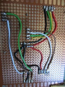
With the sketch working I wanted to get away from the jumper cables and have something more stable. So I started work on attaching everything to a piece of perf board. First try wasn't very elegant
See photo.
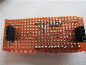
As you can see it isn't pretty and also it needed solder both sides which is nigh on impossible.
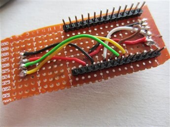
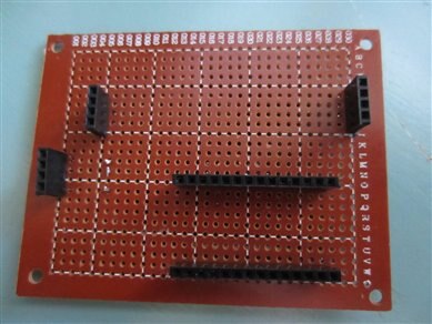
This is my second attempt which I think is much better and it also includes the RGB LED as an status indicator..
Enclosure
So now I need an enclosure. I thought about disguising it as a Bluetooth speaker but in the end I want to hide the device out of sight if I can, so I opted for a plain box.
I drew it on FREECAD and printed it.

I have made the box bigger than required because I am thinking about how I could incorporate a pir so I have left enough room for whatever I come up with. I am hiding the OLED display under the lid (I will probably remove it and just leave the socket empty for future use as this will save energy). I realised that this would mean there was no visual indiction as to what was going on inside the box so I have made a hole in the lid to incorporate an LED. This means a slight change to the sketch and the circuit.
So the sketch change involved making the LED turn to red while waiting for connection, Change to green once working and change to blue while in halt mode.
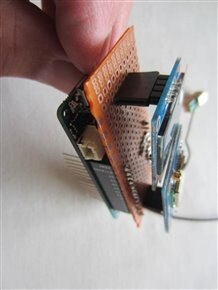
Here is the circuit board installed in the enclosure. One problem with my enclosure design is that the gap between the battery and the usb socket is too small and only one of my usb power supplies fits. I have redesigned the enclosure slightly larger but haven't had time to print it.

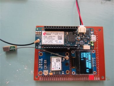
So this is it working
And finally it working in its enclosure

I have tested it in the car going shopping but because of the lockdown I haven't been able to go to the caravan to test it. So I don't know what kind of impact the caravan will have on the signals or where I will have to site it in the caravan to make it work.
I think it works quite nicely but time will tell.
Future Considerations
I guess I shouldn't hint at the fact that my project isn't perfect. Yes it works and I think it works well. However like most things it could be improved or at least upgraded.
First upgrade I think should be the PIR mentioned earlier and I think this would be a good early warning if a text message was sent if the PIR is triggered.
Secondly I was thinking that it is impossible to hitch up a caravan without changing its angle so a gyroscope could be a good addition.
I also wondered about number spoofing. I really think this is unlikely with my caravan as its value isn't that high but some of the more expensive units might make a thief think a bit harder. That said, firstly they would need to know my number which is possible I suppose because I get calls from the accident solicitors but they would also need the Cara-duino number which can be kept secret. If they somehow got the number, one solution would be to modify the script to include a password. This got me thinking a bit more and I wondered if the sketch should warn if a valid text is received from an unauthorised number. Fairly simple to do but again number spoofing could trick that. I don't know how number spoofing is done and how hard it is do I don't really know if this should even be a consideration.
Top Comments
-

dubbie
-
Cancel
-
Vote Up
0
Vote Down
-
-
Sign in to reply
-
More
-
Cancel
Comment-

dubbie
-
Cancel
-
Vote Up
0
Vote Down
-
-
Sign in to reply
-
More
-
Cancel
Children