


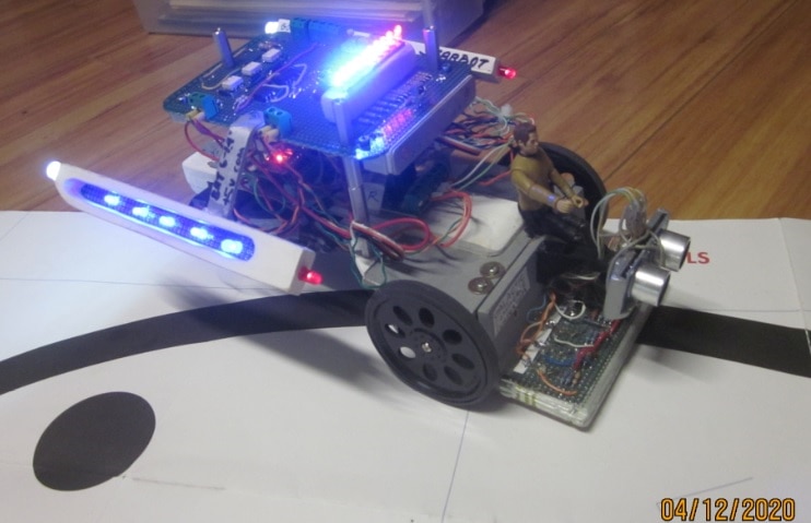
I had several old homemade robots that were out of date and needing maintenance.
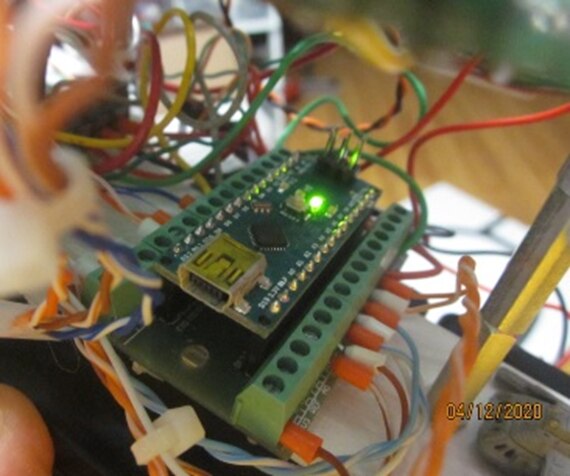
Thanks to NanoRama, the old robots have a new Arduino Nano brain and renewed life.
The Arduino Nano has analog IO which can be used to read the voltage across a IR phototransistor to determine how much IR is reflected off a white sheet of paper.
The white paper is a good reflector, black is a poor reflector of IR light.
That is how line following works in a nutshell.
Reading the phototransistor voltage analog allows the software to determine hysteresis and filtering of the detection signal, and also use a PID if wanting to ride on the edge of a black line.
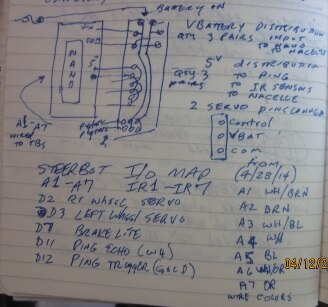
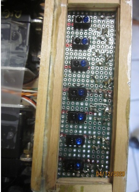
The Star Trek style nacelle IO card was originally built for a Parallax BoEbot. This card has a bunch of LEDS, which the higher power ones use opto couplers or SSRs to drive them. This card also has an IR receiver wired.
When using the Arduino Nano provided by this contest, the new bootloader in the Arduino IDE needs selected.

Without further adieu, here are photos, diagrams and code for the project.
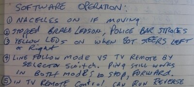
In my operation description, item 4 says select IR remote control or line follow per HW switch. That was simplified, just press ON on the remote controller to activate IR remote control mode.
Please reply to me if interested in the detailed schematics.


// Starbot_FullFeaturesWorks.ino includes both IRRemotecontrol
// and line follower control modes
//
//Line Follower mode, an object detected by PING less than 6 inches in front
//causes a temporary zerospeed condition
//
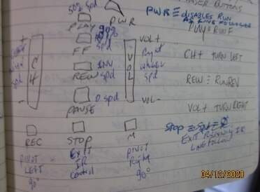
//Running by IR Remote control. Star Trek Phaser Remote, set VCR program 000.
//an object detected by PING less than 6 inches in front, STARBOT will slowly reverse
// and slightly steer right to find a clear path.
//
///from http://www.circuitbasics.com/arduino-ir-remote-receiver-tutorial/
// I commented out the LCD display part
// I changed the original values to the HEX values to the ones I recorded using IRrecvDumpV2 example.
//
// Star Trek Phaser Remote programmed with "000" code for device TV, VCR, and CBL.
// Need to do the program step on each device type (if used).
// Arduino loaded with IRrecDumpV2.ino (recPin=10)
// VCR action buttons don’t register any data in monitor page
// PWR button Code : 22DD48B7 (32 bits)
// PLAY button Code : 22DDA857 (32 bits) RUN STARBOT FWD 50% Speed
// FF Code : 22DDC837 (32 bits) RUN STARBOT FWD 95% Speed
// REW Code : 22DD9867 (32 bits) go REV INVERT In USE SPEED REFERENCES
// PAUSE Code : 22DD08F7 (32 bits) RUN ZEROSPEED
// STOP Code : 22DD28D7 (32 bits) Disable run from IR, i.e. run as line follower
// VOL+ Code : 20DF40BF (32 bits) Inc Right wheel speed
// VOL - Code : 20DFC03F (32 bits) DEC Right wheel SPEED
// Ch + Code : 22DDD827 (32 bits) Inc left wheel spd
// Ch - 22DDF807 (32 bits) dec left wheel speed
// REC Code : 22DD18E7 (32 bits) PIVOT 90 degrees left
// MUTE Code : 20DF906F (32 bits) Pivot 90 degrees right
//
//
#include <IRremote.h>
#include <Servo.h>
const int RECV_PIN = 10;
IRrecv irrecv(RECV_PIN);
decode_results results;
unsigned long key_value = 0;
Servo LeftWheel; // create servo object to control a servo
// a maximum of eight servo objects can be created
Servo RightWheel; // create servo object to control a servo
// a maximum of eight servo objects can be created
int RunByIRRemote = LOW;
int LeftSPD =90 ; //var for left side wheel speed
int RightSPD =90; //var for RHS wheel speed
int RightSpeedInUseValue = 90;
int LeftSpeedInUseValue = 90;
//// setup needed VARS --------------------------
// pinging VARs
unsigned long Pingmicroseconds =0;
unsigned long PingDistanceInches =0;
int PreviousPingDistanceInches;
int pos = 0; // variable to store the servo position
unsigned int Ping_cm; // ping distance in cm
int loopNR=0; // generic register for loops
//********
int WheelRunSpd=45; // full speed setpoint for robot 0 is zerospeed, 90 is top speed
int HardTurnWheelSpd=5;// speed setpoint of wheel that slows down to make a hard pivot turn, 0 is zerospeed, 90 is top speed
int GentleTurnWheelSpd=25;// speed setpoint of wheel that slows down to make a normal turn , 0 is zerospeed, 90 is top speed
//****
int arrayvalue=0;
int IR_Analog[8]; // analog input 0 is unused, array for the IR sensors analog value
int IR_bits[8]; // analog input 0 is unused, array for the IPR sensors analog converted to bits
void setup(){
// Serial.begin(9600);
irrecv.enableIRIn();
// irrecv.blink13(true);
RightWheel.attach(2); // attaches the servo on pin 2 to the servo object
LeftWheel.attach(3); // attaches the servo on pin 3 to the servo object , 0 = left front wheel forward
pinMode(4,OUTPUT); // Left Turn LEDs on nacelle P1, 5V to turn on, powered from Vbat
pinMode(5,OUTPUT); // right Turn LEDs on nacelle P2 , 5V to turn on, powered from Vbat
pinMode(6,OUTPUT); // rear brake LEDs on nacelle P3 , 5V to turn on, powered from Vbat
pinMode(7,OUTPUT); // warp drive LEDs on nacelle P4, 5V to turn on, powered from Vbat
pinMode(9,OUTPUT); // police bar LEDs on nacelle P7 ,5V to turn on, powered from Vbat
pinMode(13,OUTPUT); // police bar LEDs on nacelle P6, 5V to turn on, powered from Vbat
// note: pin10 is used by IRRemote.
pinMode(12, OUTPUT); // PING trigger
pinMode(11, INPUT); // PING echo
//
//pinMode(A0,INPUT); //
// // A1-A7 are wired with TRT2000 IR sensors,
pinMode(A1,INPUT); // voltage drop across IR senstive LED circuit. Low number is IR transistor ON (see white reflection)
pinMode(A2,INPUT); // High value - i.e. no light, more voltage drop (black line or no white paper)
pinMode(A3,INPUT); //
pinMode(A4,INPUT); //
pinMode(A5,INPUT); //
pinMode(A6,INPUT); //
pinMode(A7,INPUT); //
// IO Test before starting --------------------------
digitalWrite(4,HIGH);
delay (200);
digitalWrite(4,LOW);
digitalWrite(5,HIGH);
delay (200);
digitalWrite(5,LOW);
digitalWrite(6,HIGH);
delay (200);
digitalWrite(6,LOW);
digitalWrite(7,HIGH);//naccelle
delay (200);
digitalWrite(7,LOW);
digitalWrite(13,HIGH);
delay (200);
digitalWrite(13,LOW);
digitalWrite(9,HIGH);
delay (200);
digitalWrite(13,LOW);
digitalWrite(9,LOW);
}
void PING ()
{
digitalWrite(12, HIGH); // HC-SR04 pulse high TRIGGER
delayMicroseconds(10); // pauses for 10 microseconds
digitalWrite(12, LOW); // sets the TRIGGER pin off
// ECHO PIN measure microseconds taken to hear pulse, third number is wait time in microseconds( unsigned long int 0 to 4,294,967,295)
Pingmicroseconds = pulseIn(11, HIGH, 4000);
PingDistanceInches = (Pingmicroseconds/149); //formula from HC-SR04 spec sheet , assume solution is an integer
if (PingDistanceInches==0){PingDistanceInches=111;}
// 340 meters/ second * (39.37 inches per meters) =13385. inches per usec = .0133856 inches per microsecond;; 74.7 usecs/inch , multiply by 2 for send/return path
// test and debug
// Serial.print("PingDistance=");
//// Serial.print(PingDistanceInches);
// Serial.print("inches ");
// Serial.println();
}
void loop()
{
if (irrecv.decode(&results))
{
if (results.value == 0XFFFFFFFF)
results.value = key_value;
// lcd.setCursor(0, 0);
// lcd.clear();
switch(results.value){
case 0x22DD48B7: ///
// Serial.println("PWR Button Pressed");
RunByIRRemote = HIGH;
break;
case 0x22DDA857: //// if PLAY button pressed, STARbot speed ref is 50% forward
// Serial.println("Pressed PLAY");
if (RunByIRRemote == HIGH){
RightSPD =(115); // WheelRunSpd counts above 90, 90 is zero , +180 is full spd Fwd
LeftSPD =(65); // WheelRunSpd counts below 90, 90 is zero, 0 is full spd reverse
digitalWrite(7,HIGH);//naccelle
}
break;
case 0x22DDC837 : //// if FF button pressed, STARbot speed ref is 95% forward
// Serial.println("Pressed FF");
if (RunByIRRemote == HIGH){
RightSPD =(135); // WheelRunSpd counts above 90, 90 is zero , +180 is full spd Fwd
LeftSPD =(45); // WheelRunSpd counts below 90, 90 is zero, 0 is full spd reverse
digitalWrite(7,HIGH);//naccelle
}
break;
case 0X22DD9867 : // if REW button pressed, STARbot in use speed ref is reversed
// Serial.println("Pressed REW");
if (RunByIRRemote == HIGH){
RightSpeedInUseValue = RightSPD;
LeftSpeedInUseValue = LeftSPD;
RightSPD = (90-(RightSpeedInUseValue-90)); // WheelRunSpd counts above 90, 90 is zero , +180 is full spd Fwd
LeftSPD =(90+(90-LeftSpeedInUseValue)); // WheelRunSpd counts below 90, 90 is zero, 0 is full spd reverse
if (RightSPD <0) {RightSPD=0;} // limit the max value
if (RightSPD >180) {RightSPD=180;} // limit the max value
if (LeftSPD <0) {LeftSPD=0;} // limit the max value
if (LeftSPD >180) {LeftSPD=180;} // limit the max value
}
break;
case 0x22DD08F7:
// if Pause button pressed, STARbot speed ref is zeroed
// Serial.println("PAUSE");
if (RunByIRRemote == HIGH){
RightSPD =(90); // WheelRunSpd counts above 90, 90 is zero , +180 is full spd Fwd
LeftSPD =(90); // WheelRunSpd counts below 90, 90 is zero, 0 is full spd reverse
digitalWrite(7,LOW);//naccelle
}
break ;
case 0x22DD28D7: // if STOP button pressed, STARbot control by phaser is disabled
// Serial.println("STOP PB");
RunByIRRemote = LOW;
//digitalWrite(7,LOW);
break ;
case 0x20DF40BF: // if VOL+ button pressed, STARbot increases right wheel speed
// Serial.println("VOL+");
if (RunByIRRemote == HIGH){
RightSPD =(RightSPD+5); // WheelRunSpd counts below 90, 90 is zero, 0 is full spd reverse
if (RightSPD <0) {RightSPD=0;} // limit the max value
if (RightSPD >180) {RightSPD=180;} // limit the max value
}
break ;
case 0x20DFC03F : // if VOL- button pressed, STARbot decreases right wheel speed
// Serial.println("VOL MINUS");
if (RunByIRRemote == HIGH){
RightSPD =(RightSPD-5); // WheelRunSpd counts below 90, 90 is zero, 0 is full spd reverse
if (RightSPD <0) {RightSPD=0;} // limit the max value
if (RightSPD >180) {RightSPD=180;} // limit the max value
}
break ;
case 0x22DDD827 : // if CH+ button pressed, STARbot increases left wheel speed
// Serial.println("CH+");
if (RunByIRRemote == HIGH){
LeftSPD =(LeftSPD-5); // WheelRunSpd counts below 90, 90 is zero, 0 is full spd reverse
if (LeftSPD <0) {LeftSPD=0;} // limit the max value
if (LeftSPD >180) {LeftSPD=180;} // limit the max value
}
break ;
case 0x22DDF807 : // if CH- button pressed, STARbot decreases left wheel speed
// Serial.println("CH minus");
if (RunByIRRemote == HIGH){
LeftSPD =(LeftSPD+5); // WheelRunSpd counts below 90, 90 is zero, 0 is full spd reverse
if (LeftSPD <0) {LeftSPD=0;} // limit the max value
if (LeftSPD >180) {LeftSPD=180;} // limit the max value
}
break ;
case 0x22DD18E7 : // if REC button pressed, STARbot pivots left
// Serial.println("REC");
if (RunByIRRemote == HIGH){
RightSpeedInUseValue = RightSPD; // temporarily save values in use
LeftSpeedInUseValue = LeftSPD; // temporarily save values in use
RightSPD =(135); // WheelRunSpd counts above 90, 90 is zero , +180 is full spd Fwd
LeftSPD =(90); // WheelRunSpd counts below 90, 90 is zero, 0 is full spd reverse
RightWheel.write(RightSPD); // wired to D2 , 0 is full speed fwd, run @ 7/9 of top speed to allow for overspeed
LeftWheel.write(LeftSPD); // wired to D3, // WheelRunSpd counts below 90, 90 is zero, 0 is full spd reverse
delay (1000);
RightSPD = RightSpeedInUseValue ; // restore spd values to before pivot command
LeftSPD = LeftSpeedInUseValue ; // restore spd values to before pivot command
}
break ;
case 0x20DF906F : // if MUTE button pressed, STARbot pivots right
// Serial.println("MUTE");
if (RunByIRRemote == HIGH){
RightSpeedInUseValue = RightSPD; // temporarily save values in use
LeftSpeedInUseValue = LeftSPD; // temporarily save values in use
RightSPD =(90); // WheelRunSpd counts above 90, 90 is zero , +180 is full spd Fwd
LeftSPD =(45); // WheelRunSpd counts below 90, 90 is zero, 0 is full spd reverse
RightWheel.write(RightSPD); // wired to D2 , 0 is full speed fwd, run @ 7/9 of top speed to allow for overspeed
LeftWheel.write(LeftSPD); // wired to D3, 180 is full speed fwd run @ 7/9 of top speed to allow for overspeed
delay (1000);
RightSPD = RightSpeedInUseValue ; // restore spd values to before pivot command
LeftSPD = LeftSpeedInUseValue ; // restore spd values to before pivot command
}
break ;
}
key_value = results.value;
irrecv.resume();
} // end of IR Receiver case logic
////continuance of loop execution after IR remote scan is completed
//// if RunByRemote is LOW, the line folllower code will execute
if (RunByIRRemote == LOW )
///while (RunByIRRemote == LOW)
{
/// read all the IR sensors & store in an array
IR_Analog[1]= analogRead(A1); // read the input pin
IR_Analog[2]= analogRead(A2); // read the input pin
IR_Analog[3]= analogRead(A3); // read the input pin
IR_Analog[4]= analogRead(A4); // read the input pin
IR_Analog[5]= analogRead(A5); // read the input pin
IR_Analog[6]= analogRead(A6); // read the input pin
IR_Analog[7]= analogRead(A7); // read the input pin
for(loopNR = 1 ; loopNR < 8; loopNR += 1) // read all the IR line detectors
{
// this converts the analog value to a bit value with hysterysis and stores that result in another array
if (IR_Analog[loopNR]<200) {IR_bits[loopNR]=0;} ///value == 0 white
if (IR_Analog[loopNR]>600) { IR_bits[loopNR]=1;} ///value== 1, black
// Serial.print ("IR");
// Serial.print (loopNR);
// Serial.print ("=");
// Serial.println (IR_Analog[loopNR]);
// Serial.print ("IRbit = ");
// Serial.println (IR_bits[loopNR]);
// delay (10);
}
arrayvalue = 0; //clear out that VAR last value
//// read analog ins, convert bits, then construct a 7 bit word. Spreadsheet IRSensorMeasurements.xlsx provides mapping of values VS steer action
arrayvalue = ((IR_bits[1]*1)+ (IR_bits[2]*2)+(IR_bits[3]*4)+ (IR_bits[4]*8)+(IR_bits[5]*16)+(IR_bits[6]*32)+(IR_bits[7]*64));
// these line reading values have the wheels go the same speed
if ((arrayvalue == 8) || ((arrayvalue >19)&& (arrayvalue <24)) || ((arrayvalue >27)&& (arrayvalue <32)) || ((arrayvalue >43)&& (arrayvalue <48)) || (arrayvalue ==65) ||((arrayvalue >96)&& (arrayvalue <104)) || (arrayvalue == 126))
{
digitalWrite(4,LOW);//left turn signal off
digitalWrite(5,LOW);//right turn signal off
RightSPD = (90+WheelRunSpd); // WheelRunSpd counts above 90, 90 is zero , +180 is full spd Fwd
LeftSPD=(90-WheelRunSpd); // WheelRunSpd counts below 90, 90 is zero, 0 is full spd rev
// Serial.print ("IR follower array value = ");
// Serial.println (arrayvalue);
// Serial.println ("go forward");
// delay(30);
digitalWrite(7,HIGH);// turn on nacelle lights
}
// these line reading values make a HARD left turn, left wheel slows way down, right wheel keeps up speed if arrayvalue = 1,2 or 3
else if ((arrayvalue >-1)&&(arrayvalue<4))
{
RightSPD =(90+WheelRunSpd); // WheelRunSpd counts above 90, 90 is zero , +180 is full spd Fwd
LeftSPD =(90-HardTurnWheelSpd); // WheelRunSpd counts below 90, 90 is zero, 0 is full spd reverse
digitalWrite(4,HIGH);//left turn signal on
// Serial.print ("array value = ");
// Serial.println (arrayvalue);
// Serial.println ("hard left");
delay(10);
digitalWrite(4,LOW);//left turn signal off
}
// these line reading values make a left turn, left wheel slows , right wheel keeps up speed
else if (((arrayvalue >3)&&(arrayvalue<16)) || ((arrayvalue >31)&&(arrayvalue<44))||((arrayvalue >63)&&(arrayvalue<80))||((arrayvalue >122)&&(arrayvalue<127)))
{
RightSPD =(90+WheelRunSpd); // WheelRunSpd counts above 90, 90 is zero , +180 is full spd Fwd
LeftSPD =(90-GentleTurnWheelSpd); // WheelRunSpd counts below 90, 90 is zero, 0 is full spd reverse
digitalWrite(4,HIGH);//left turn signal on
// Serial.print ("array value = ");
// Serial.println (arrayvalue);
// Serial.println ("hard left");
//delay(30);
digitalWrite(4,LOW);//left turn signal off
}
//stop the wheels if only see white or only see black, mens the robot is not on a line
else if ((arrayvalue == 0)||(arrayvalue == 127)) ////dumbass forgot == again
{
digitalWrite(4,LOW);//left turn signal off
digitalWrite(5,LOW);//right turn signal off
RightSPD=90;
LeftSPD=90;
// Serial.print ("array value = ");
// Serial.println (arrayvalue);
// Serial.println ("STOP");
//delay(30);
digitalWrite(7,LOW); // turn off nacelle lights to indicate off track condition
digitalWrite(6,HIGH); //D6 are brake LEDs
delay(2000);
digitalWrite(7,HIGH);// turn on nacelle lights
digitalWrite(6,LOW); //D6 are brake LEDs
delay(300);
}
// these line reading values make a HARD RIGHT turn, right wheel slows way down, left wheel keeps up speed if arrayvalue = 32,64,80,96
else if ((arrayvalue ==32)||(arrayvalue=64)||(arrayvalue ==80)||(arrayvalue=96))
{
RightSPD =(90+HardTurnWheelSpd); // WheelRunSpd counts above 90, 90 is zero , +180 is full spd Fwd
LeftSPD =(90-WheelRunSpd); // WheelRunSpd counts below 90, 90 is zero, 0 is full spd reverse
digitalWrite(5,HIGH);//right turn signal on
// Serial.print ("array value = ");
// Serial.println (arrayvalue);
// Serial.println ("hard left");
delay(10);
digitalWrite(5,LOW);//right turn signal off
}
else // these line reading values make a right turn, right wheel slows down , left wheel at runspeed BUT if a value fails this turns right
{
RightSPD =(90+GentleTurnWheelSpd); // WheelRunSpd counts above 90, 90 is zero , +180 is full spd Fwd
LeftSPD=(90-WheelRunSpd); // WheelRunSpd counts below 90, 90 is zero, 0 is full spd rev
digitalWrite(5,HIGH);//right turn signal on
//Serial.print ("array value = ");
//// Serial.println (arrayvalue);
// Serial.println ("hard right");
delay(10);
digitalWrite(5,HIGH);//right turn signal off
}
}
// ** PING for obstruction while running as an line follower,
// the ping stops the robot while there is an obstruction in
// front of it. Whn obstruction is removed, then it continues on **
PING();
if ((PingDistanceInches<6)&(PreviousPingDistanceInches<6))
{
if (RunByIRRemote==LOW)///if running linefollower mode , robot needs to stop
{
RightWheel.write(90); // wired to D2 , 0 is full speed fwd, run @ 7/9 of top speed to allow for overspeed
LeftWheel.write(90); // wired to D3, 180 is full speed fwd un @ 7/9 of top speed to allow for overspeed
LeftSPD = 90;
RightSPD = 90;
}
if (RunByIRRemote==HIGH)///if running IRRemote mode , robot needs to back up and turn slightly
{
RightSpeedInUseValue = RightSPD; // temporarily save values in use
LeftSpeedInUseValue = LeftSPD; // temporarily save values in use
RightWheel.write(85); // wired to D2 , 180 is full speed fwd, run @ 7/9 of top speed to allow for overspeed
LeftWheel.write(100); // WheelRunSpd counts below 90, 90 is zero, 0 is full spd reverse
LeftSPD = 100;
RightSPD = 65;
}
for (int i=1; i<10; i++)
{
digitalWrite(4,LOW);//left turn signal off
digitalWrite(5,LOW);//right turn signal off
//
digitalWrite(6,HIGH); //D6 are brake LEDs
digitalWrite(13,HIGH); //D13 police LEDs red/blue
digitalWrite(9,LOW); //D9 police LEDs blue/red
delay (150);
digitalWrite(13,LOW);
digitalWrite(9,HIGH);
delay (150);
}
digitalWrite(6,LOW);
digitalWrite(9,LOW);
if (RunByIRRemote==HIGH)
{RightSPD = RightSpeedInUseValue ; // restore spd values to before pivot command
LeftSPD = LeftSpeedInUseValue ; // restore spd values to before pivot command
}
}
PreviousPingDistanceInches = PingDistanceInches;
/////////end of stop when object pings too close
// Serial.print ("RunByIRRemote flag= ");
// Serial.println (RunByIRRemote);
// Serial.print ("LeftSPD = ");
// Serial.println (LeftSPD);
RightWheel.write(RightSPD); // // WheelRunSpd counts above 90, 90 is zero , +180 is full spd Fwd
LeftWheel.write(LeftSPD); // wired to D3, // WheelRunSpd counts below 90, 90 is zero, 0 is full spd reverse
}
Top Comments
-

dubbie
-
Cancel
-
Vote Up
+2
Vote Down
-
-
Sign in to reply
-
More
-
Cancel
-

robogary
in reply to dubbie
-
Cancel
-
Vote Up
+2
Vote Down
-
-
Sign in to reply
-
More
-
Cancel
-

dubbie
in reply to robogary
-
Cancel
-
Vote Up
+1
Vote Down
-
-
Sign in to reply
-
More
-
Cancel
-

robogary
in reply to dubbie
-
Cancel
-
Vote Up
+3
Vote Down
-
-
Sign in to reply
-
More
-
Cancel
-

robogary
in reply to dubbie
-
Cancel
-
Vote Up
+1
Vote Down
-
-
Sign in to reply
-
More
-
Cancel
Comment-

robogary
in reply to dubbie
-
Cancel
-
Vote Up
+1
Vote Down
-
-
Sign in to reply
-
More
-
Cancel
Children