element14 Community
element14 Community
    Register Log In
  • Site
  • Search
  • Log In Register
  • About Us
  • Community Hub
    Community Hub
    • What's New on element14
    • Feedback and Support
    • Benefits of Membership
    • Personal Blogs
    • Members Area
    • Achievement Levels
  • Learn
    Learn
    • Ask an Expert
    • eBooks
    • element14 presents
    • Learning Center
    • Tech Spotlight
    • STEM Academy
    • Webinars, Training and Events
    • Learning Groups
  • Technologies
    Technologies
    • 3D Printing
    • FPGA
    • Industrial Automation
    • Internet of Things
    • Power & Energy
    • Sensors
    • Technology Groups
  • Challenges & Projects
    Challenges & Projects
    • Design Challenges
    • element14 presents Projects
    • Project14
    • Arduino Projects
    • Raspberry Pi Projects
    • Project Groups
  • Products
    Products
    • Arduino
    • Avnet Boards Community
    • Dev Tools
    • Manufacturers
    • Multicomp Pro
    • Product Groups
    • Raspberry Pi
    • RoadTests & Reviews
  • Store
    Store
    • Visit Your Store
    • Choose another store...
      • Europe
      •  Austria (German)
      •  Belgium (Dutch, French)
      •  Bulgaria (Bulgarian)
      •  Czech Republic (Czech)
      •  Denmark (Danish)
      •  Estonia (Estonian)
      •  Finland (Finnish)
      •  France (French)
      •  Germany (German)
      •  Hungary (Hungarian)
      •  Ireland
      •  Israel
      •  Italy (Italian)
      •  Latvia (Latvian)
      •  
      •  Lithuania (Lithuanian)
      •  Netherlands (Dutch)
      •  Norway (Norwegian)
      •  Poland (Polish)
      •  Portugal (Portuguese)
      •  Romania (Romanian)
      •  Russia (Russian)
      •  Slovakia (Slovak)
      •  Slovenia (Slovenian)
      •  Spain (Spanish)
      •  Sweden (Swedish)
      •  Switzerland(German, French)
      •  Turkey (Turkish)
      •  United Kingdom
      • Asia Pacific
      •  Australia
      •  China
      •  Hong Kong
      •  India
      •  Korea (Korean)
      •  Malaysia
      •  New Zealand
      •  Philippines
      •  Singapore
      •  Taiwan
      •  Thailand (Thai)
      • Americas
      •  Brazil (Portuguese)
      •  Canada
      •  Mexico (Spanish)
      •  United States
      Can't find the country/region you're looking for? Visit our export site or find a local distributor.
  • Translate
  • Profile
  • Settings
Op-Amp-a-Palooza
  • Challenges & Projects
  • Project14
  • Op-Amp-a-Palooza
  • More
  • Cancel
Op-Amp-a-Palooza
Forum I'm still struggling to apply my limited knowledge of op amps... so I've created a problem to solve... but need your help.
  • Blog
  • Forum
  • Documents
  • Events
  • Polls
  • Files
  • Members
  • Mentions
  • Sub-Groups
  • Tags
  • More
  • Cancel
  • New
Join Op-Amp-a-Palooza to participate - click to join for free!
Actions
  • Share
  • More
  • Cancel
Forum Thread Details
  • State Not Answered
  • Replies 23 replies
  • Subscribers 41 subscribers
  • Views 3632 views
  • Users 0 members are here
Related

I'm still struggling to apply my limited knowledge of op amps... so I've created a problem to solve... but need your help.

BigG
BigG over 3 years ago

I can follow along other peoples projects but it quickly becomes apparent that I do not fully grasp the fundamentals when I try and solve a problem of my own.

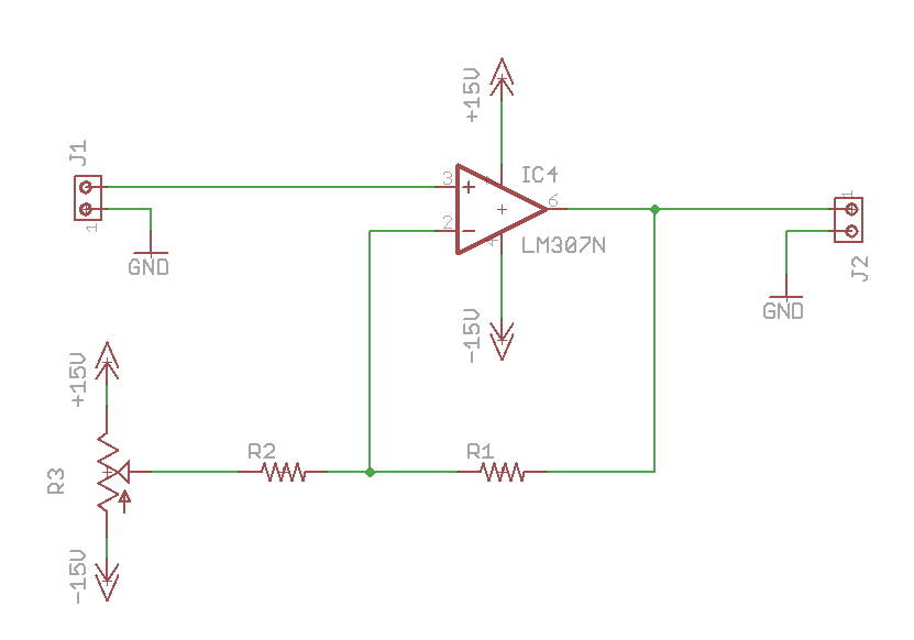
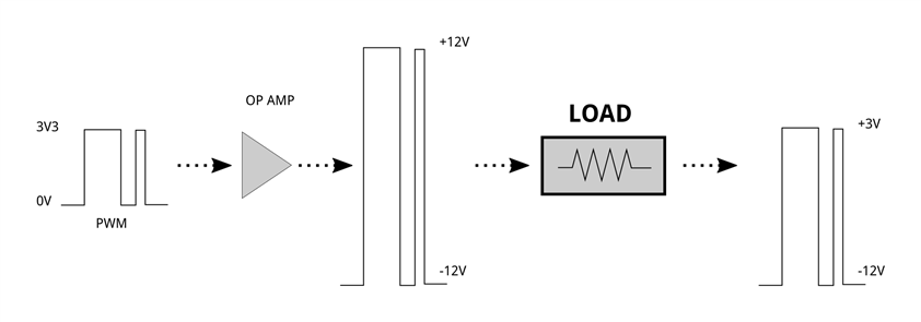
So here is my own problem I'm trying to solve, as shown below:

image

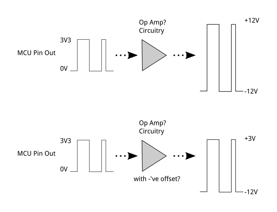
I have two scenarios. I think the first one is fairly easy, but it is knowing how to achieve the 2nd that is more challenging, especially if you wish to say use the same op amp and even the same circuit the 1st.

How does one go about this?

As per usual, I very quickly try and over-complicate matters... like when spotting these types... Transresistance amplifiers... and wondering whether I should/could use these...

Anyway, no doubt this is a very straightforward problem for the experts.

I look forwards to getting some tips.

Thanks.

C://

  • Sign in to reply
  • Cancel

Top Replies

  • beacon_dave
    beacon_dave over 3 years ago +7
    This might be of help ? 'Designing Gain and Offset in Thirty Seconds' https://www.ti.com/lit/an/sloa097/sloa097.pdf
  • scottiebabe
    scottiebabe over 3 years ago +6
    .
  • beacon_dave
    beacon_dave over 3 years ago in reply to fmilburn +4
    More in-depth coverage in this book: Op Amps for Everyone https://www.elsevier.com/books/op-amps-for-everyone/carter/978-0-12-811648-7 The calculators don't appear to be on ti.com anymore but can be…
Parents
  • dougw
    0 dougw over 3 years ago

    Good references. Figure 7 can be modified to use a pot to adjust the offset:

    R1 adjusts the voltage swing, R3 adjusts the offset.

    image

    • Cancel
    • Vote Up +2 Vote Down
    • Sign in to reply
    • Verify Answer
    • Cancel
  • BigG
    0 BigG over 3 years ago in reply to dougw

    Brilliant. Thanks dougw

    I provided some detail of me working through that document. Kinda got stuck, but I appreciate your answer.

    I was hoping that my two options could be selected through software using same circuit, so not sure a resistor pot will work in this case.

    • Cancel
    • Vote Up +1 Vote Down
    • Sign in to reply
    • Verify Answer
    • Cancel
  • shabaz
    0 shabaz over 3 years ago in reply to BigG

    The op-amp guides are super-useful, but they address op-amps only, whereas your solution could involve other techniques in combination. But, more information is needed (e.g. what is the load, and is your stimulus AC (e.g. square wave or PWM) or will you want the output to work for DC too, and also do you wish the input to take values between 0V and 3.3V (e.g. DAC inside MCU) or is it a digital logic output? (this can affect the design, depends on if you wish to have a linear response, or not).

    • Cancel
    • Vote Up +2 Vote Down
    • Sign in to reply
    • Verify Answer
    • Cancel
  • BigG
    0 BigG over 3 years ago in reply to shabaz
    shabaz said:
    But, more information is needed (e.g. what is the load, and is your stimulus AC (e.g. square wave or PWM) or will you want the output to work for DC too, and also do you wish the input to take values between 0V and 3.3V (e.g. DAC inside MCU) or is it a digital logic output? (this can affect the design, depends on if you wish to have a linear response, or not).

    A very valid point. For background, I had spotted the other day a rather unusual signalling design, which is used in electrical vehicle charging controller's control pilot signal wire. This looks to be a PWM generated signal. It is used to communicate charging states between a vehicle and the charging station. I'm not here trying to change the design. I was merely trying to simulate this and learn about op amps at the same time.

    Of course, if it could be done another way using an MCU to generate these different signals, I would be keen to know too. For example, I did wonder if RS232 could be used instead.

    image

    image

    source: https://www.jsae.or.jp/en/publications/yearbook_e/2014/docu/28_industry_standards.pdf

    • Cancel
    • Vote Up 0 Vote Down
    • Sign in to reply
    • Verify Answer
    • Cancel
Reply
  • BigG
    0 BigG over 3 years ago in reply to shabaz
    shabaz said:
    But, more information is needed (e.g. what is the load, and is your stimulus AC (e.g. square wave or PWM) or will you want the output to work for DC too, and also do you wish the input to take values between 0V and 3.3V (e.g. DAC inside MCU) or is it a digital logic output? (this can affect the design, depends on if you wish to have a linear response, or not).

    A very valid point. For background, I had spotted the other day a rather unusual signalling design, which is used in electrical vehicle charging controller's control pilot signal wire. This looks to be a PWM generated signal. It is used to communicate charging states between a vehicle and the charging station. I'm not here trying to change the design. I was merely trying to simulate this and learn about op amps at the same time.

    Of course, if it could be done another way using an MCU to generate these different signals, I would be keen to know too. For example, I did wonder if RS232 could be used instead.

    image

    image

    source: https://www.jsae.or.jp/en/publications/yearbook_e/2014/docu/28_industry_standards.pdf

    • Cancel
    • Vote Up 0 Vote Down
    • Sign in to reply
    • Verify Answer
    • Cancel
Children
  • BigG
    0 BigG over 3 years ago in reply to BigG

    Actually shabaz your question mentioning load is very good. Got me thinking that I might've got this all wrong. Could it be that the resistance load changes, depending on state, thereby creating the different output voltages. Hence the output voltage from the op amp is simply constant with PWM etc. and you need to measure output voltage after the load and not before.

    image

    • Cancel
    • Vote Up 0 Vote Down
    • Sign in to reply
    • Verify Answer
    • Cancel
  • shabaz
    0 shabaz over 3 years ago in reply to BigG

    I wasn't thinking that, but was thinking of switching different levels using MOSFETs, but would really depend on the use-case.

    Since you mention this is vehicle-related, I'm 95% sure they will have done it by switching voltage levels inside whatever application-specific IC they are using. I know nothing about car interfaces however : ( but sometimes, industrial communication type stuff, will use high voltage levels, and will have a robust interface that may rely on MOSFETs or BJTs to switch the levels. Just thinking, one idea could be to use a DAC output from the microcontroller, and use an op-amp to amplify across the superset of the expected voltage range for all pulses, and then you can set the DAC output to a smaller range to get the output to be what is needed (this assumes the DAC can be controlled fast enough for the waveform you want).

    • Cancel
    • Vote Up 0 Vote Down
    • Sign in to reply
    • Verify Answer
    • Cancel
  • BigG
    0 BigG over 3 years ago in reply to shabaz

    Thanks for the feedback. Funny that, I was only looking at DAC's earlier today to try and see if they could be used but couldn't decide if it makes life simpler.

    shabaz said:
    this assumes the DAC can be controlled fast enough for the waveform you want).

    To answer your question, it needs to be a square wave at 1kHz. Only the duty cycle is a variable.

    As such, I am actually now moving away from op amps and moving towards either using comparators or transistors with level shifting. For the latter, I was using SparkFun's RS232 Shifter breakout board as guidance. It is nice and simple. Or would MOSFETS work better in this case.

    I'm still figuring out the basics about comparators so put these aside. I stumbled across this YouTube video (published a few weeks ago), which has helped somewhat. I loved the way he refers to his trusty components as jellybeans. LOL.

    https://www.youtube.com/watch?v=c5M8P6oe9xY

    In terms of trying to mimic the specific charging application, I discovered a few more useful bits of info online. So it looks like the real question is "where do you measure the output" in your circuit.

    Looking at the various states, this is what I need to measure.

    So when the controller (i.e. MCU) is powered on it will use a GPIO output to pulse a signal at 1kz (it also needs to be able to change the duty cycle of this pulsed signal - used for a different purpose). This signal then has to be amplified so that when at VCC (assume its 3V3) it is pulled up to 12V and when at 0V it is pulled down to -12V.

    The MCU must then use another pin as an INPUT to determine that the amplified signal is in fact at 12V. This logic tells the MCU that nothing is connected.

    Then when a vehicle connects, it applies a load and closes out our loop to ground (in this case protective earth).

    The info I found suggests that a fixed resistor value is used to create a voltage drop so that our MCU input pin now reads a lower value which is equivalent to 9V. This indicates that a vehicle is connected. The vehicle also uses a diode in the circuit so that the -12V is blocked and thus the MCU will only read a 0V.

    When the vehicle is ready to charge another fixed resistor value is used (doesn't give us configuration used) so that the MCU input pin now reads an equivalent value to 6V. And similarly the same again to get to 3V.

    If at any stage, assuming this is during the 3 connected phases (but maybe it applies to the unconnected state too), the MCU measures a -12V then this is a failure scenario.... I'm thinking this gives us clues as to where the input connection fits within the charging circuitry.

    So from an op amp perspective, its standard amplification to plus / minus 12V.

    From a circuit perspective it's trying to work out where to make the connection for the MCU input pin. I cannot figure this out. I'm guessing it is before the op amp and somehow tied into the op amp feedback loop.

    Would love to know.

    • Cancel
    • Vote Up +1 Vote Down
    • Sign in to reply
    • Verify Answer
    • Cancel
  • shabaz
    0 shabaz over 3 years ago in reply to BigG

    I see.. I don't entirely understand the scheme, but am thinking a H-bridge could be part of the solution if desired. Something like a H-bridge powered from +12V (no need for -12V supply) and then the two wires output from the H-Bridge effectively are +-12V as the legs of the bridge are switched. So, by using normal 3.3V logic, you'll get the +-12V output waveform. Then if you are expecting the far side to load it to a lower voltage, you'd want a resistor in series with the H-bridge output, to allow the voltage drop to occur. I don't know what resisor value though, since it depends on the remote side resistor value too.

    Then, you could use the op-amp to monitor the output levels, perhaps even low-pass filter it, so that you receive an average voltage level (if that's what is required) to read with the microcontroller ADC. Or comparators could be used too, then the ADC isn't needed.

    • Cancel
    • Vote Up 0 Vote Down
    • Sign in to reply
    • Verify Answer
    • Cancel
  • BigG
    0 BigG over 3 years ago in reply to shabaz

    You've read my mind... I've been pondering about how best to get -12V. So thanks for the valued input.

    • Cancel
    • Vote Up 0 Vote Down
    • Sign in to reply
    • Verify Answer
    • Cancel
element14 Community

element14 is the first online community specifically for engineers. Connect with your peers and get expert answers to your questions.

  • Members
  • Learn
  • Technologies
  • Challenges & Projects
  • Products
  • Store
  • About Us
  • Feedback & Support
  • FAQs
  • Terms of Use
  • Privacy Policy
  • Legal and Copyright Notices
  • Sitemap
  • Cookies

An Avnet Company © 2025 Premier Farnell Limited. All Rights Reserved.

Premier Farnell Ltd, registered in England and Wales (no 00876412), registered office: Farnell House, Forge Lane, Leeds LS12 2NE.

ICP 备案号 10220084.

Follow element14

  • X
  • Facebook
  • linkedin
  • YouTube