


What's Ponq?
A false start

I'd been wondering exactly what to so for my PYNQ embedded vision project. I'd started out with an attempt to identify racing kayaks as they crossed the finish line, but I was having a lot of trouble with the OCR side of things in OpenCV and I also realised this project was not really going to use the strengths of the Xilinx FPGA. It could probably be done just as well on a Raspberry Pi. So - back to the drawing board.
A new idea
Then my son came home with a project he'd done in the one day of school a week that he's doing. Due to the cancellation of Wimbledon tennis this year, they'd been challenged to make up their own substitute. He'd come up with pushing a ball back and forth across a table and scoring much like table tennis. One sentence from his poster struck me - Someone or something must be a scoreboard.
I imagined an overhead view of the "court" with the Pynq-Z2 tracking the movement of the ball and updating the score. I then thought back to the first video game I ever used - the classic (if you're old enough) Pong. I imagined a Pong-like score for each player calculated automatically and overlayed on top of a video feed of the game.


Most importantly, I can imagine that a reasonable amount of this - the scoreboard generation, the overlay, the video pre-processing being done in the Programmable Logic and actually making use of the Zynq in the Pynq. The name, of course had to be Ponq.
Creating Ponq
1. Generating the scoreboard IP
Stage one was to create a Pong-like score board and place this over the incoming HDMI video. As you'd expect, I did a bit of Googling to see how to approach this. And also as you'd expect, Adam Taylor's projects came top of the list! I found something quite interesting adding a numeric overlay on a video. The approach taken here was to generate a new video signal and use the Video Mixer IP to put this over a separate video feed. Whilst this is obviously one good way to do this, I decided to take a different approach for a couple of reasons. Firstly, I didn't just want to copy someone else work. Secondly, I'd already create a "posterize" IP using Vivado HLS that worked on an incoming video stream. I decided that my IP should amend an incoming feed rather that creating a new one. During my research, I also found some interesting post about cropping incoming video which is worth a read.
The initial problem I had was to shift from my initial IP which just cared about a pixel at a time to one that worked on a frame. I started with the approach taken in the cropping technique which, knowing the size of the frame went more or less "for y = 1 to 480" and "for x = 1 to 640". Whilst this worked fine for image files that were fed in through the test bench, this seemed to lose sync when used on a video feed. I'm guessing that the horizontal and vertical porch weren't taken into account. My test code initially displayed a cross using code like:
void scoreboard_osd(AXI_STREAM& s_axis_video,AXI_STREAM& m_axis_video, int hsize_in, int vsize_in)
{
#pragma HLS INTERFACE axis register both port=s_axis_video
#pragma HLS INTERFACE axis register both port=m_axis_video

ap_axiu<24, 1, 1, 1> video;

    for(int y = 0; y < vsize_in ; y ++)
    {
           for(int x = 0; x < hsize_in ; x ++)
           {
                 s_axis_video >> video;

                 if ((x >= 100 && x < 110) || (y >= 100 && y < 110)) {
                    video.data = 0x808080;
                 }

                 m_axis_video << video;
         }
    }
}
However, you can see that the output would often be wonky. You may notice it's displayed on top of what appears to be a Raspberry Pi desktop. This is just because this was the most convenient source of a 640x480 video feed that I had to hand!

I eventually decided to actually make use of the incoming sync data from the video signal. In addition to the pixel data there are:
keep - this is 1 if the pixel is part of the visible screen, 0 otherwise
user - this is 1 for the start of the video frame
last - this is 1 for the end pixel in a line.
By using these my code was independent on both the size of the frame and also the position it happened to start in. I also found that there was a function called empty() that told me whether there was more data to process. Ignoring this meant that it seemed to work on a video feed, but not so well on the testbench that passed a single video frame generated from an image. My final HLS code looked like this:
#include "scoreboard.h"
#include "digit.h"

int x;
int y;

#define SCALE 5
#define TOP 30
#define BOTTOM (TOP+7*SCALE)

#define START1_10 (320-15*SCALE)
#define END1_10 (START1_10+5*SCALE)

#define START1_01 (START1_10+6*SCALE)
#define END1_01 (START1_01+5*SCALE)

#define START2_10 (320+4*SCALE)
#define END2_10 (START2_10+5*SCALE)

#define START2_01 (START2_10+6*SCALE)
#define END2_01 (START2_01+5*SCALE)

#define WHITE 0xffffff;

//Top Level Function
void scoreboard_osd(AXI_STREAM& s_axis_video, AXI_STREAM& m_axis_video, int score1, int score2)
{
#pragma HLS CLOCK domain=default
#pragma HLS INTERFACE ap_ctrl_none port=return
#pragma HLS INTERFACE axis register both port=s_axis_video
#pragma HLS INTERFACE axis register both port=m_axis_video
#pragma HLS INTERFACE s_axilite register port=score1 clock=control
#pragma HLS INTERFACE s_axilite register port=score2 clock=control

ap_axiu<24, 1, 1, 1> video;

if (score1 > 99) score1=99;
if (score2 > 99) score2=99;
unsigned char score1_10 = score1/10;
unsigned char score1_01 = score1 - (score1_10*10);
unsigned char score2_10 = score2/10;
unsigned char score2_01 = score2 - (score2_10*10);


while (!s_axis_video.empty()) {
    s_axis_video >> video;

    // Only change visible pixels
    if (video.keep) {

        // Start of frame
        if (video.user) {
            x = 0;
            y = 0;
        }

        // Main logic
        if (y >=TOP && y < BOTTOM && x >=START1_10 && x < END2_01) {
            if (draw_digit(x, y, START1_10, END1_10, score1_10, false))
                video.data = WHITE;
            if (draw_digit(x, y, START1_01, END1_01, score1_01, true))
                video.data = WHITE;
            if (draw_digit(x, y, START2_10, END2_10, score2_10, false))
                video.data = WHITE;
            if (draw_digit(x, y, START2_01, END2_01, score2_01, true))
                video.data = WHITE;
        }
        x++;


        // End of line
        if (video.last) {
            x = 0;
            y++;
        }
    }


    m_axis_video << video;
    }
}


bool draw_digit(int x, int y, int start, int end, unsigned char number, bool showZero) {


    if (number > 9) return false; // safety
    if (!showZero && number == 0) return false;


    if (x>=start && x < end) {
        unsigned char px = (x-start)/SCALE;
        unsigned char py = (y-TOP)/SCALE;
        return digit[number][py][px];
    }
    return false;


}
And this is the very useful testbench code that can take a 640 x 480 image file and run it hrough as if it's a single video frame. This was inspired by the crop tutorial and made iterating the code much faster.
#include "scoreboard.h"
#include <hls_opencv.h>

int main (int argc, char** argv) {

    // Load data in OpenCV image format
    IplImage* src = cvLoadImage("in.png");

    //Get input Image size
    CvSize size_in = cvGetSize(src);

    //Set output image size
    CvSize size_out;
    size_out.width = size_in.width;
    size_out.height = size_in.height;

    //Create Destination image
    IplImage* dst = cvCreateImage(size_out, src->depth, src->nChannels);

    //Create the AXI4-Stream
    AXI_STREAM src_axi, dst_axi;

    // Convert OpenCV format to AXI4 Stream format
    IplImage2AXIvideo(src, src_axi);

    // Call the function to be synthesized
    scoreboard_osd(src_axi, dst_axi, 0, 106);

    // Convert the AXI4 Stream data to OpenCV format
    AXIvideo2IplImage(dst_axi, dst);

    // Standard OpenCV image functions
    cvSaveImage("out.png", dst);

    cvReleaseImage(&src);
    cvReleaseImage(&dst);

    return 0;
}
My digits were creating using an array of booleans. I decide to go with a nice 80s low-resolution 7x5 pixel blocky font. The Pynq could manage much more (including different colours and even alpha blending, but that wasn't what I was after. Here you can see how simple it was to define a zero.
// Define X and _ just so it's easier to see the digit in the text file.
#define X true
#define _ false

// Simple 7x5 digits 0 to 9
bool digit[10][7][5] = {
  {
    { X, X, X, X, X },
    { X, _, _, _, X },
    { X, _, _, _, X },
    { X, _, _, _, X },
    { X, _, _, _, X },
    { X, _, _, _, X },
    { X, X, X, X, X },
  },
 // continues for 1 to 9 in the same way...

2. Adding the scoreboard IP to our overlay.
Once the scoreboard IP had been created I started by adding it on to the pipeline we created during the workshop series. I'd previously added IP to posterize the colours coming through, so I won't go into great detail about packaging the IP. The process was much the same. I then switched from Vivado HLS to Vivado and this IP was then dropped in to the same place by posterize IP had been.
After going through the now familiar process of creating a bitstream to export over to Pynq I was ready to test it.
3. Using our IP in Pynq
One thing that didn't seem obvious was how to access my parameters - score1 and score2. There was a useful comment I found in another of Adam Taylor's blogs - "You can find the slave AXI address offset in the generated driver files for the IP block in Vivado HLS". However, there wasn't any further details. I eventually managed to find the details I needed in a file called scoreboard\scoreboard\syn\verilog\scoreboard_osd_AXILiteS_s_axi.v that told me the addresses I needed.
//------------------------Address Info-------------------
// 0x00 : reserved
// 0x04 : reserved
// 0x08 : reserved
// 0x0c : reserved
// 0x10 : Data signal of score1
//        bit 31~0 - score1[31:0] (Read/Write)
// 0x14 : reserved
// 0x18 : Data signal of score2
//        bit 31~0 - score2[31:0] (Read/Write)
// 0x1c : reserved
// (SC = Self Clear, COR = Clear on Read, TOW = Toggle on Write, COH = Clear on Handshake)
I initially thought that the following code would work. It runs just fine but it does nothing. There must be a way to get this working so the IP is easier to use, but right now I'm not sure how.
osd.score1 = 93
osd.score2 = 46
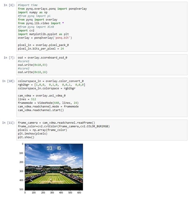
I was very happy to see that I could now set the two scores in my Python code overlayed on my video feed. (My Raspberry Pi is now displaying a photo of Wimbledon.)
4. Displaying the score on via HDMI out
The next stage was to display the video with the score overlay on a HDMI monitor. I took inspiration from this Xilinx blog showing how to generate HDMI output on the Pynq using the pattern generator. There's also a nice blog by here by yuricts covering similar ground. PYNQ Z2: Getting Up and Running - Tea Storm . I decide to split the video stream straight from the front end. One side would have the overlay added and head out to the Z2's HDMI out. The other side was better without the overlay as it was going to be processed to find the ball and work out the scoring.
The IP required for this are as follows:
| IP | Function |
|---|---|
| AXI4-Stream Broadcaster | This splits the AXI stream into two copies |
| Video Timing Controller | In our case this generates the timing signals required. It can also be configured to detect these signals if required. |
| AXI4-Stream to Video Out | This takes the stream and the timing from the Timing Controller and generates RGB video signal |
| RGB to DVI Video Encoder | As the name implies, this takes RGB video and generates the DVI signal we're going to push out over HDMI. |
This is the relevant part of the (not quite working yet) block design starting from where the broadcaster takes a "copy" of the incoming HDMI stream. The outputs on the right are direceted to the appropriate HDMI pins through the standard Pynq Z2 constraints file.

The Xilinx example is for Vivado 2018.1 (which is not one of the 4 versions of Vivado I have installed) but it wasn't too hard to create it for later versions. The structure of the IP is as shown. The thing I found hardest to get working properly was the clocking. I was banging my head against conflicts between IP that was clocked at 100MHz (for AXI control) and other than was clocked at 142MHz (for the video stream). I somehow missed that the pixel clock for the RGB to DVI should be clocked at 40MHz and was stuck there for a while. Tying it to the PixelClock from HDMI in synthesized OK but caused routing errors. Once I had the block design synthesizing OK I then spend many head-scratching hours with just nothing on the HDMI output. I have converted this guide to HDMI to to work with Vivado 2019.1 and can happily generate an 800x600 output. I have removed my own IP and have the HDMI-to-Pynq block design we created in the work shop processing 800x600 HDMI in from a Raspberry Pi. However, I just can't get the video stream from the Color Convert IP displaying on the HDMI out. I know it's OK as Pynq can display it. The only difference I can see is that the Pynq video stream is working at 142MHz and the HDMI out example uses 100MHz, but I've matched this to the AXI4-Stream to Video Out.
After a very helpful Zoom screen sharing session with Adam Taylor, it turns out that there are a couple of oddities when dealing with a real incoming video stream, as opposed to the on generated by IP such as the Test Pattern Generator. The TPG creates a nice clean stream of pixel data. HDMI however, tends to come in irregular bursts. It seems that these burst weren't quite stable enough for the AXI4-Stream to Video Out to get a lock and to push data out on its vid_io_out port. Connecting the onboard LEDs showed that locked remained low and underflow was worryingly high. Increasing the hysteresis (i.e. buffering) in this piece of IP finally gave some output although this tended to flicker out to a blank screen every few seconds. Al least I now had something coming through. Another little quirk is that if you use a Stream Broadcaster then neither output gets any data if one of the isn't accepting input. In this case, until you call readframe() in Pynq, the video out will also receive no data.
Unfortunately this flickering screen was the best I could get. I tried varying the hysteresis. I tried adding an AXI4 FIFO IP but at best this slightly lengthened the time before flickering to black. Making any other changes - including adding the Scoreboard IP I'd created - only created instability in the output video stream.
Taking a look at some video processing projects for the Zybo Z7, it seems that the way to go is to load frames into memory using DMA - as we're doing here for Pynq's benefit - and to restream these out again from RAM. I assume that way any little gaps are managed by showing the relevant part of the previous frame. The FPGA dream of manipulating pixels on the fly is a little unrealistic. You can read them that way, you can generate them that way, but being the "man in the middle" requires a big chunk of RAM as a safety net.
Conclusion
Well, this project has in some ways been a failure and in others a success. I failed to create the live Pong-like scoring for my boys' real-life tennis game. (Luckily I never told them what I was doing so no promises were broken and no children disappointed.) In that respect I can be classed as a fail.
However, there was nobody waiting for this project. There's no disappointed customer. As far as I'm concerned the real purpose of this project was to increase my understanding of both Pynq and embedded video processing. This has certainly been a success. I learned a lot about Pynq. In some ways I like Pynq. On the flip side, I find that the increase in the time taken to run newly synthesized IP is a disadvantage over using a simple C program in Vivado SDK. Creating the bistream takes long enough but when you then have to copy it over, restart the kernel, sometimes restart the Pynq device, it takes even longer. I've learned a lot about OpenCV - including the fact that I find this less compelling than the FPGA side of things.
What I feel is most significant is that I've also found a much better understanding of Vivado HLS, and creating your own IP for use in Vivado. I have run through this before when road testing the Zybo Z7 but that did at times feel a little like following some instructions without understanding them - especially some of the directives. I'm definitely going to revisit that and the Pcam 5C. I also had to find out a lot more about the intricacies of creating a block design, including a better understanding of clocking and the use AXI to control and address IP.
So, this project has been enjoyable, frustrating, surprising, but certainly educational. Regardless of the disappointing final result, I can't help but feel pleased to have done it. In the end, that's all that really matters.
Top Comments