


WARNING: DO NOT TRY TO REPLICATE THIS UNLESS YOU ARE WILLING TO TAKE THE RISK OF BREAKING YOUR PSU!
Introduction
Rigol recommends calibrating the Rigol DP832 power supply unit (PSU) (Figure 1) at least once a year, and since my PSU's calibration date was 5 years old, I thought it would be a good time to recalibrate it. Before calibrating the PSU, I decided to evaluate it so that I could check if it was still in spec.
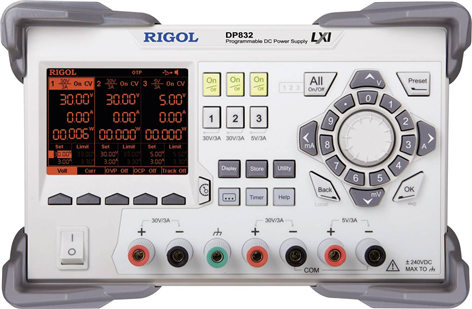
Figure 1: Rigol DP832 [Source: Rigol].
While looking for the specs, I found some discrepancies between the annual accuracy shown in the datasheet (Table 1) and in the performance verification manual (Table 2):
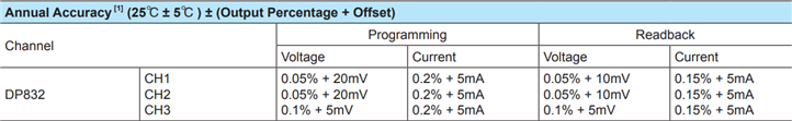
Table 1: Annual accuracy according to the datasheet [Source: Rigol].
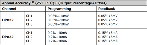
Table 2: Annual accuracy according to the performance verification manual [Source: Rigol].
So I arbitrarily chose to test the instrument against the following accuracy limits:
| Item |
Annual accuracy (25℃ ±5℃) ±(Output percentage + offset) |
|---|---|
| Voltage programming | 0.05% + 10mV |
| Voltage readback | 0.05% + 5mV |
| Current programming | 0.2% + 5mA |
| Current readback | 0.15%+ 5mA |
My previous experience with Rigol's test equipment software and remote control was not good, they were unstable and not usable at all. I was surprised to find that now the TCP/IP link worked very well.
To control the PSU I used Python with PyVisa and the following simple PSU SCPI commands:
- *RST
Restores the PSU to the factory settings and clears the error queue.
- :OUTP
Enables or disables the output of the specified channel.
- :APPL
Sets the voltage and current for the specified channel.
- :MEAS:ALL?
Queries the voltage, current and power measured on the output terminal of the specified channel.
The PSU was connected to a Keithley DMM6500 which was controlled through simple TSP commands (which I've already shown in my Keithley Bench Digital Multimeter - Review). Two type of connections have to be made for each channel, to measure voltage (Figure 2) and current (Figure 3).
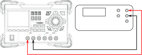
Figure 2: Voltage measurement [Source: Rigol].
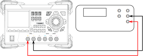
Figure 3: Current measurement [Source: Rigol].
Each channel contains 4 calibration items:
- Programmed voltage (V-DAC)
- Programmed current (I-DAC)
- Readback voltage (V-ADC)
- Readback current (I-ADC)
To measure the accuracy of the instrument, 12 calibration items need to be evaluated.
Pre-calibration accuracy
Accuracy was measured by performing full voltage and current sweeps at each channel with a 1 s delay at each sweep step and measurement. 0.1 V steps were used in the voltage sweep, and 0.01 A steps in the current sweep. The following table shows the obtained results:
Pre-cal V-DAC V-ADC I-DAC I-ADC
------------------------------------------------------
Channel 1: ±12.8 mV ±8.1 mV ±0.8 mA ±1.5 mA
Channel 2: ±12.4 mV ±10.4 mV ±2.2 mA ±2.0 mA
Channel 3: ±4.6 mV ±2.5 mV ±4.1 mA ±3.6 mA
The following 2 figures show the programmed and readback voltage and current errors:

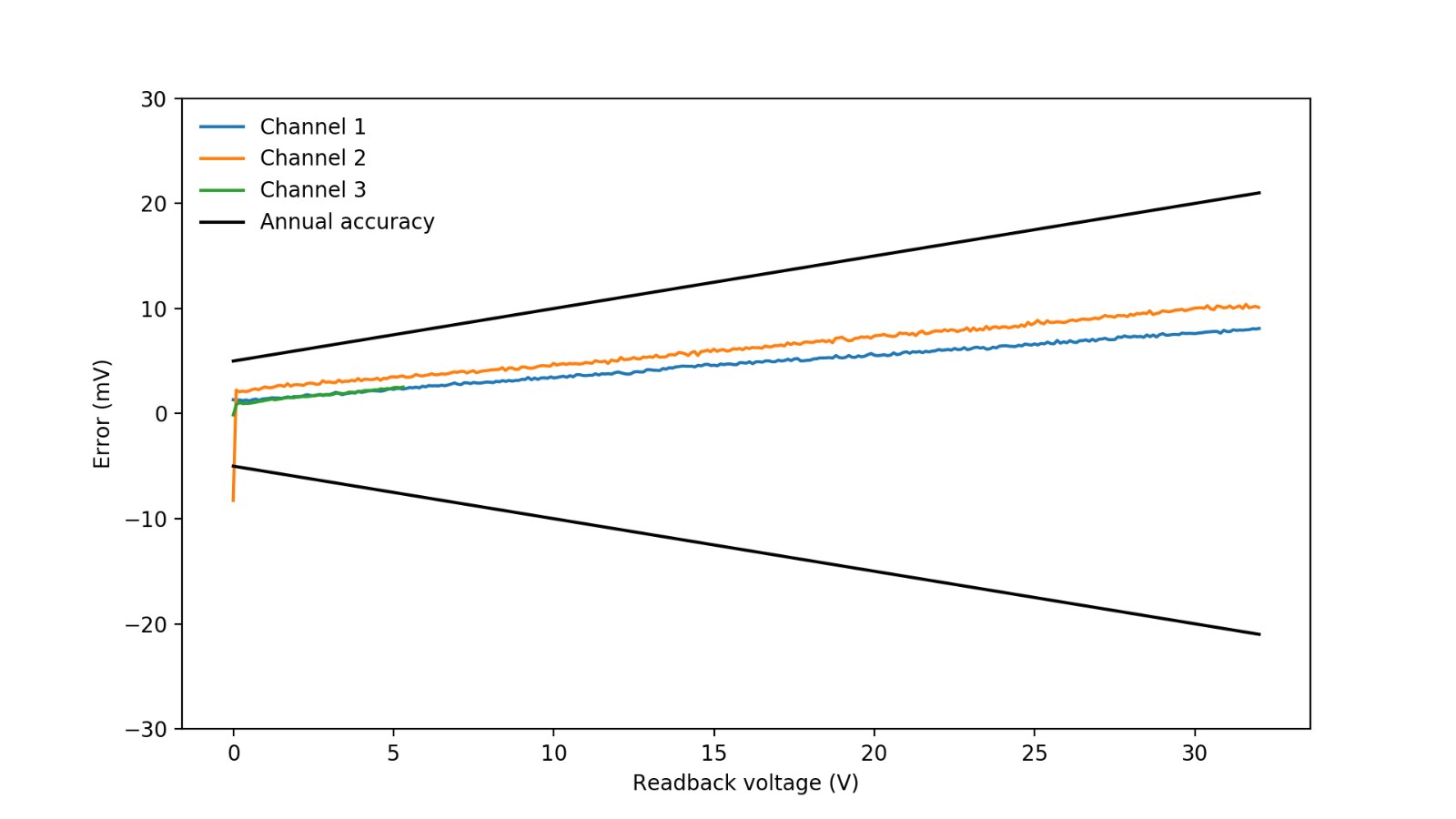
Figure 4: Programmed voltage and readback voltage error plots.
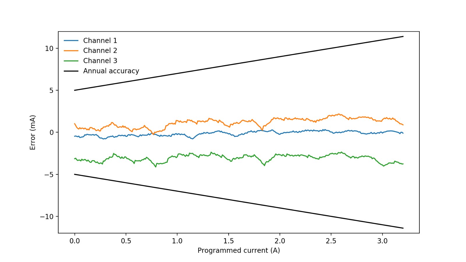

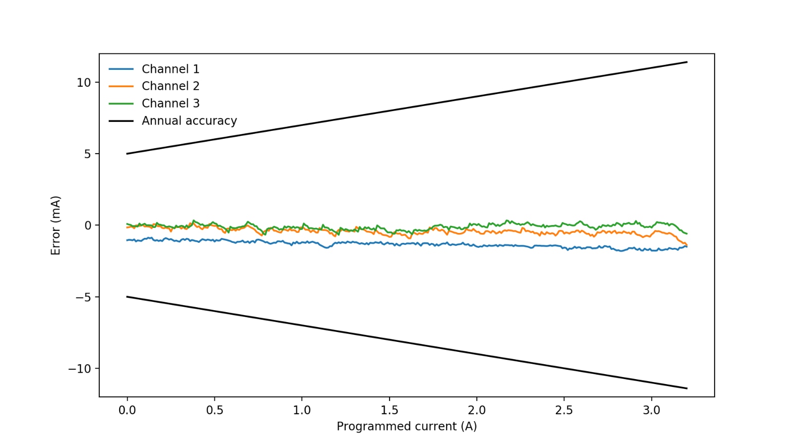
Figure 5: Programmed voltage and readback current error plots.
Everything looked fine, with the exception of the channel 2 readback voltage, which at 0 V gets slightly out off spec. The reason that it gets out of spec is that when the PSU is programmed to output 0 V, it actually outputs ~-8 mV, which is then read back as a clamped 0 V. A similar situation occurs with channel 3 in the readback current plot, but it does not get out of spec there.
Calibration
Rigol provides a calibration manual that shows how to manually calibrate the PSU. To calibrate it, the 4 calibration items (V-DAC, V-ADC, I-DAC, I-ADC) need to be evaluated at different "calibration points" (Figure 6). When a "cal point" is selected the PSU generates an arbitrary voltage/current output that depends on the cal point ID, this output has to be measured with a DMM and manually entered in the table. The procedure needs to be repeated for every "cal point" of the table until it's complete. Since the PSU has 3 channels and there are 4 calibration items, 12 tables need to be filled to fully calibrate the PSU. There is a total of 180 values that have to be entered, which makes the process slow,and error prone.

Figure 6: Calibration table [Source: Rigol].
Luckily there is a better approach through the usage of SCPI commands. Members of the eevblog reverse engineered the PSU calibration SCPI commmands and published an SCPI calibration user guide. Although a good starting point, this guide has some minor errors and misses some important details, such as that the number of calibration points and values can be set arbitrarily. Lets take a look at the commands that I used on my calibrator program:
- :CAL:START
Begins the calibration of the specified channel.
- :CAL:END
Ends the calibration and saves the specified date.
- :CAL:CLEAR
Clears the calibration table.
- :CAL:SET
Sets the PSU output to the specified voltage/current and enters a calibration point output value in the table.
- :CAL:MEAS
Sets the DMM measured voltage/current value to the specified calibration point.
The number of calibration points, and their output values were set by trial and error. Some calibration point values increased the error at the low end of the voltage/current values in a non-trivial way. After some testing, I finally decided to used a total of 386 calibration points to perform a full calibration.
Here is a text output sample of an ongoing calibration:
Connected to PSU at 'TCPIP0::192.168.0.35::inst0::INSTR'
Connected to DMM at 'TCPIP0::192.168.0.30::inst0::INSTR'
press Enter to begin calibration...
Calibrating Ch1 V-DAC
[1/65] V-DAC: 0.250, V-DMM: -0.05259
[2/65] V-DAC: 0.500, V-DMM: 0.19608
[3/65] V-DAC: 1.000, V-DMM: 0.69401
[4/65] V-DAC: 1.500, V-DMM: 1.19042
[5/65] V-DAC: 2.000, V-DMM: 1.68867
[6/65] V-DAC: 2.500, V-DMM: 2.18614
[7/65] V-DAC: 3.000, V-DMM: 2.68230
[8/65] V-DAC: 3.500, V-DMM: 3.17921
[9/65] V-DAC: 4.000, V-DMM: 3.67903
[10/65] V-DAC: 4.500, V-DMM: 4.17686
[11/65] V-DAC: 5.000, V-DMM: 4.67444
[12/65] V-DAC: 5.500, V-DMM: 5.17170
[13/65] V-DAC: 6.000, V-DMM: 5.66934
[14/65] V-DAC: 6.500, V-DMM: 6.16577
[15/65] V-DAC: 7.000, V-DMM: 6.66192
[16/65] V-DAC: 7.500, V-DMM: 7.15350
[17/65] V-DAC: 8.000, V-DMM: 7.64920
[18/65] V-DAC: 8.500, V-DMM: 8.14618
[19/65] V-DAC: 9.000, V-DMM: 8.64358
Post-calibration accuracy
After performing a full calibration its time to compare the pre-calibration with the post-calibration results:
Pre-cal V-DAC V-ADC I-DAC I-ADC
------------------------------------------------------
Channel 1: ±12.8 mV ±8.1 mV ±0.8 mA ±1.5 mA
Channel 2: ±12.4 mV ±10.4 mV ±2.2 mA ±2.0 mA
Channel 3: ±4.6 mV ±2.5 mV ±4.1 mA ±3.6 mA
Post-cal V-DAC V-ADC I-DAC I-ADC
------------------------------------------------------
Channel 1: ±2.3 mV ±0.5 mV ±1.8 mA ±1.0 mA
Channel 2: ±4.2 mV ±0.7 mV ±1.4 mA ±0.4 mA
Channel 3: ±0.8 mV ±0.4 mV ±0.7 mA ±0.4 mA
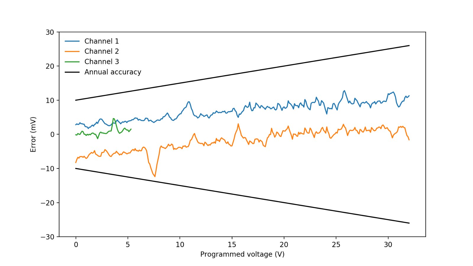
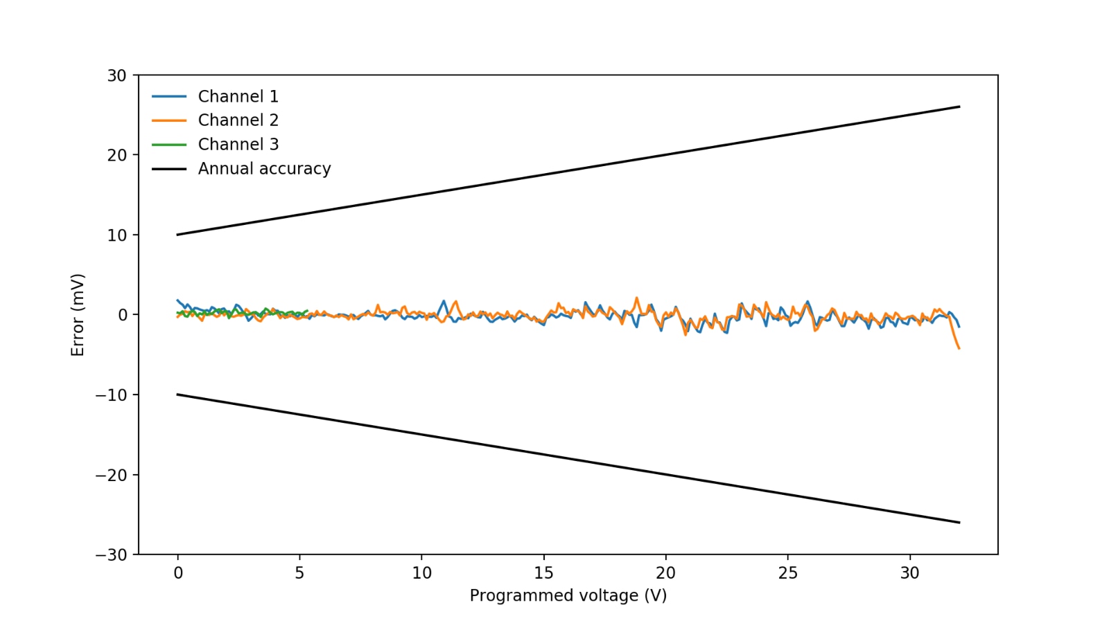
Figure 7: Pre- and post-calibration programmed voltage error plots.

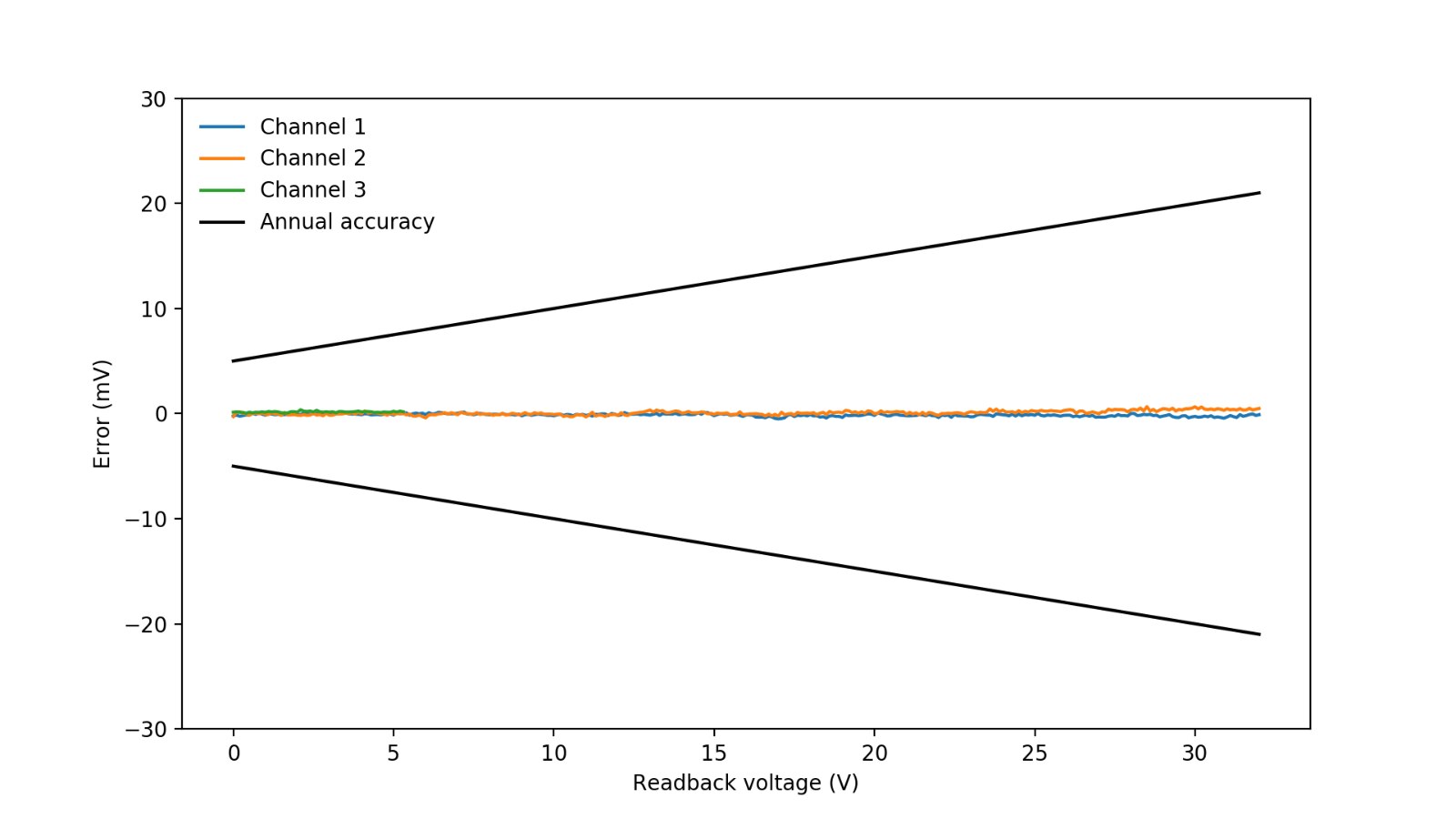
Figure 8: Pre- and post-calibration readback voltage error plots.

<html><head><title>Jive SBS</title></head>
<body><font face="arial,helvetica,sans-serif">
<b>Error</b><br><font size="-1">
An general error occurred while processing your request.
</font></font></body></html>
Figure 9: Pre- and post-calibration programmed current error plots.
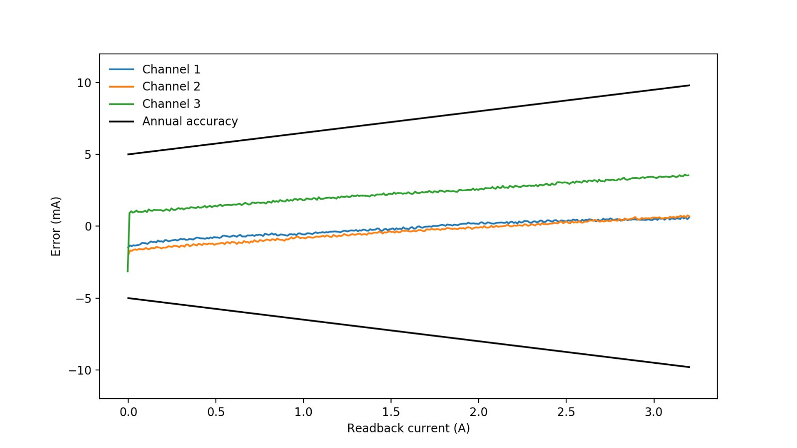
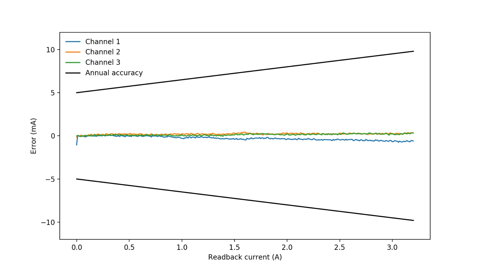
Figure 10: Pre- and post-calibration readback current error plots.
The post-calibration accuracy increased in all cases except one: the programmed current for channel 1, which I suspect was caused by temperature variations. I found the programmmd current calibration/measurement to be quite tricky because heating of the PSU affects the current output. And since PSU temperature varies quite a bit during normal operation, how close the output is to the programmed values varies during the operation of the instrument. For example if all of a sudden a lot of current is sourced, it will take probably a few minutes for the PSU output to stabilize.
Source code
All the code was uploaded to GitHub. The code structure is as follows:
Psu.py
Defines the class Psu that represents the DP832.
Dmm.py
Defines the class Dmm that represents the Keithley DMM6500. This is the class that should be modified if one wants to implement a different DMM.
Calibrate.py
Contains the function that performs the calibration.
Measure.py
Contains the function that performs the measurements.
ClearCalibration.py
Clears all the calibration tables (useful when tables get corrupted).
CalibrateSingle.py
Calibrates a single channel current or source programming and readback.
CalibrateAll.py
Calibrates the complete instrument.
MeasureSingle.py
Measures the accuracy of a single channel current or voltage source programming and readback, and then results on the screen.
MeasureAll.py
Measures the accuracy of the complete instrument, and saves the results into a file.
PlotAccuracy.py
Reads the "MeasureAll" output file and generates plots.
Conclusions
Instrument calibration can be expensive and require sending instruments to calibration labs. Here I showed an automated alternative that requires very little effort and produces acceptable results. I also showed a way to measure and evaluate the 4 calibration items to help decide when to recalibrate the PSU. All the source code will be made available on GitHub as soon as I fix some minor issues and test the programs in more depth.
Top Comments
-

ralphjy
-
Cancel
-
Vote Up
+2
Vote Down
-
-
Sign in to reply
-
More
-
Cancel
Comment-

ralphjy
-
Cancel
-
Vote Up
+2
Vote Down
-
-
Sign in to reply
-
More
-
Cancel
Children