


|
For Project 14's Restoration and Repair month, I'm going to service a Philips GA-212 Electronic turntable that needs some TLC.
In this post, I'll check the overall health of the electronic circuit: power supply voltage and related signals. |

In this blog, all photos are mine. The exerpts from the service manuals come from vinylengine.com.
Supply Voltage
"Thou shalt measure voltages."
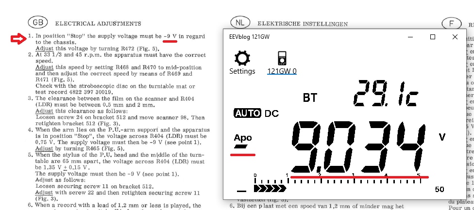
I have worked on this turntable earlier. When I opened it, I had measured the voltage and it was down to less than -7 V, while -9 V is expected.
It turned out that the two electrolytic capacitors on the PCB board were dead. Not uncommon for Philips electrolytics of that time.
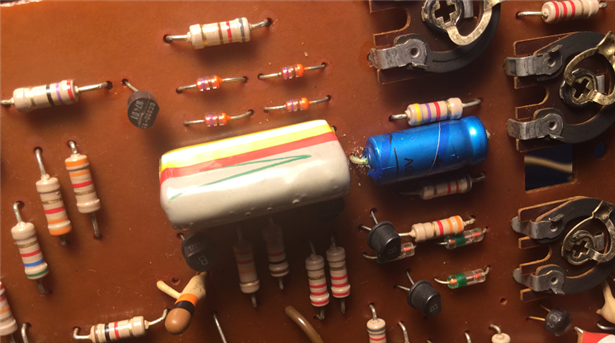
I replaced them and the power moved to a respectable to -8.85 V.


-8.85 V is good. Good enough. But the service manual says -9 V.
So I adjusted the trimmer until the specified voltage was set.

Here's the result. Very close to the expected level.
Auto Switch-Off LDR
The auto switch-off doesn't work. It's part of the start / stop circuit of the turntable.
The LDR is mounted under a light bulb that's always on when the TT is powered.
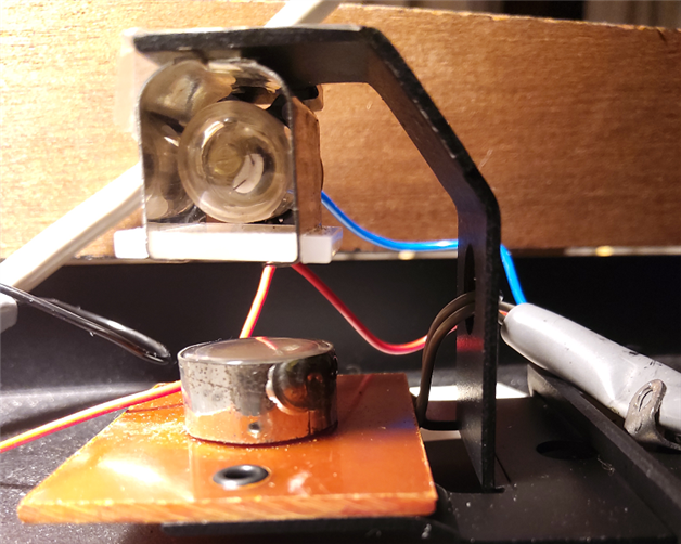
When the arm reaches the end of the record, an optical filter blocks the light reaching the LDR, and changes its resistance.

If you look at the optical filter, you'll notice that it has a funnel-form light lock.
This is a nifty trick. The filter moves very slow over the LDR. A groove per turn.
But because the filter narrows exponential, and there's a high-pass filter after the circuit, the table will only switch off when the narrow part of the filter is reached.

You put the table in START by activating either 33 or 45 RPM (more on that circuit later). Note that the power source is -9 V.
The signal for that arrives via either R532 (33) or R542 (45).
The circuit is held in that state until either the STOP capacitive touch button is used, or the LDR brings TS425 out of conduction.
I knew that the stop circuit works, because the capacitive circuit works. The LDR stop doesn't though.
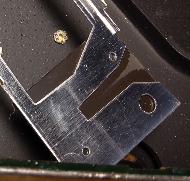
That's when I detected that someone had a go at the circuit before me. Look at the pins of trimmer R465:
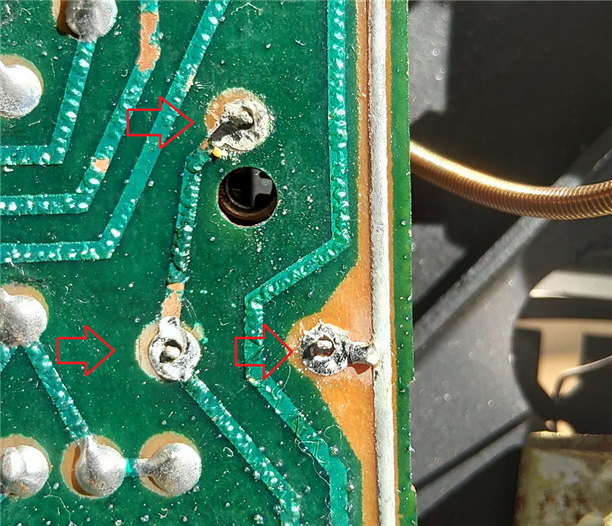
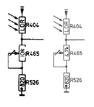
I think that the previous service tech was confused by the service manual. The trimmer is a 4K7 one but the schematic says 10K.
However, a later revision of the service manual is in line with my TT.
I can understand that this confused the repair person and that he tried to replace it with a 10K to no avail ...
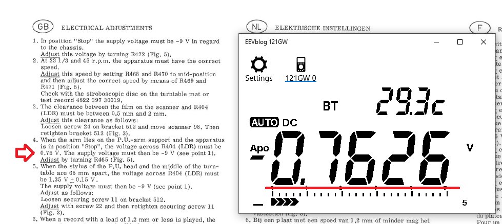
Anyways, I soldered the 4K7 one properly and trimmed the LDR level as per spec: 0.75 V.
Thoughts About the Speed Switch Circuit
At that same time I did a first overhaul, I also replaced the light bulbs in the capacitive touch buttons. They were blown.
This isn't something you '"just can do". The lamps resistance plays a part in the discrete flip-flops that lets you select the speed.
An interesting circuit. I left away the start / stop sub-circuit in the middle. It's described earlier in this post.

The two speed controls are capacitive touch switches with a light bulb underneath them.
The bulb under the 33 RPM button will light up when that's the selected speed.
The 45 one in case that the table runs at 45 RPM.
The default status, not shown here, is the off-position.
You can see two bistable multivibrators, each controlling one speed.
In the "off" case, both multivibrators are in their "inactive" position: left transistor on, right one off.
When you touch the 33 control, it will flip the upper multivibrator.
TS426 off, TS428 on. The light LA 410 will go on. And the 33 rpm signal will activate the motor circuit for 33 RPM.
Meanwhile, the upper multivibrator (33), via D445 and R538, will lock the lower multivabrator (45). It can't be used as long as the TT is running 33 RPM.
The STOP circuit first has to be activated before you can switch speed.
The 45 RPM side works exactly the same.
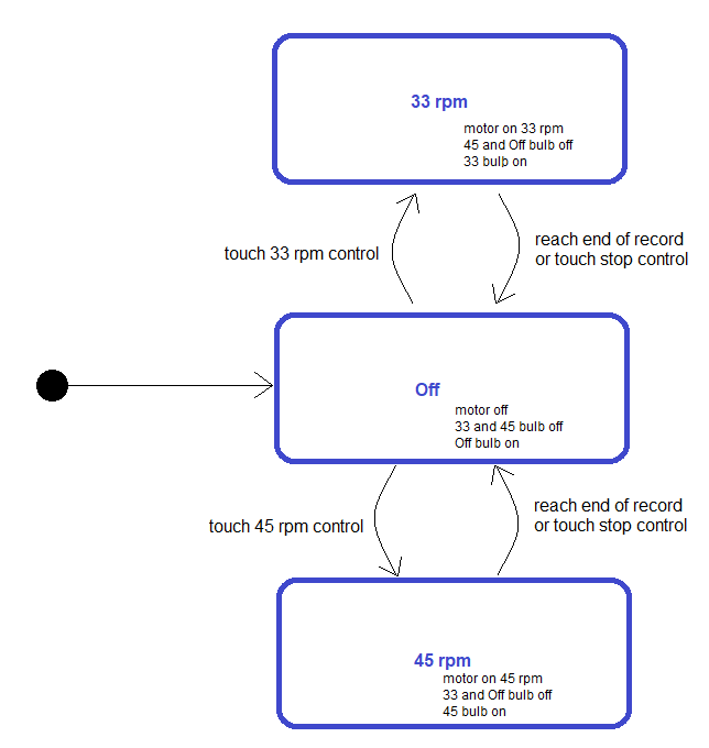
In essence, this is a state machine with 3 states: Off, 33 or 45.
You can migrate from Off to 33 by touching the 33 control
Off to 45 by touching the 45 control
Either 33 or 45 to Off by touching the Off control or blocking the LDR at the end of the record.
These days, you'd probably use a microcontroller for this?
Adjust the Speed
In the first post in this series, I created a stroboscope. That's the tool we need now to adjust the speed.

Because I adjusted the supply voltage, a little work is needed to reset the speed dials.
There are two variable resistors per speed. One on the outside, user adjustable. And a trimpot on the inside.
The inside trimmers are the calibrators. They have to be adjusted so that, when the ones on the outside are in the mid position, the speed is spot on.
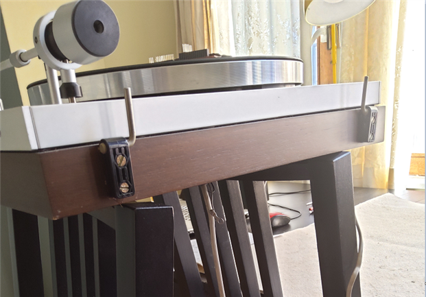
Here it gets a little tricky, because you have to turn trimmers inside the turntable while it spins.
jw0752 mentioned in a previous post that he uses a construct hanging from the ceiling. I use the backs of two chairs (very unsafe).
I balance the TT on them, with the bottom cover removed.
Then there's the fiddly part (remember to put the 2 outside potentiometers in their middle position first) where you kneel, insert a little plastic screwdriver in the correct trimmer.
Then stand up while trying to keep the screwdriver in place. Then switch the table to 45 RPM, and use a stroboscobe to check speed.
Then carefully fiddle with the little trimmer until the speed is spot on.
Once 45 is ok, do the same ith 33 RPM. Try to not knock over the whole structure ...
On the schematic below, R468 and R470 are the user accessible potentiometers. R469 and R471 are the calibration trimmers.
The circuit is worth looking at. It's a controlled DC motor circuit with feedback.

The feedback circuit is very simple.
The voltage generated by the tacho (mounted on the motor axle) is turned into a signal that will push the driving circuit when the motor slows down, and vise versa.
C730 averages the effect so that it's smooth correction.
Top Comments
-

Jan Cumps
-
Cancel
-
Vote Up
+4
Vote Down
-
-
Sign in to reply
-
More
-
Cancel
Comment-

Jan Cumps
-
Cancel
-
Vote Up
+4
Vote Down
-
-
Sign in to reply
-
More
-
Cancel
Children