element14 Community
element14 Community
    Register Log In
  • Site
  • Search
  • Log In Register
  • About Us
  • Community Hub
    Community Hub
    • What's New on element14
    • Feedback and Support
    • Benefits of Membership
    • Personal Blogs
    • Members Area
    • Achievement Levels
  • Learn
    Learn
    • Ask an Expert
    • eBooks
    • element14 presents
    • Learning Center
    • Tech Spotlight
    • STEM Academy
    • Webinars, Training and Events
    • Learning Groups
  • Technologies
    Technologies
    • 3D Printing
    • FPGA
    • Industrial Automation
    • Internet of Things
    • Power & Energy
    • Sensors
    • Technology Groups
  • Challenges & Projects
    Challenges & Projects
    • Design Challenges
    • element14 presents Projects
    • Project14
    • Arduino Projects
    • Raspberry Pi Projects
    • Project Groups
  • Products
    Products
    • Arduino
    • Avnet Boards Community
    • Dev Tools
    • Manufacturers
    • Multicomp Pro
    • Product Groups
    • Raspberry Pi
    • RoadTests & Reviews
  • Store
    Store
    • Visit Your Store
    • Choose another store...
      • Europe
      •  Austria (German)
      •  Belgium (Dutch, French)
      •  Bulgaria (Bulgarian)
      •  Czech Republic (Czech)
      •  Denmark (Danish)
      •  Estonia (Estonian)
      •  Finland (Finnish)
      •  France (French)
      •  Germany (German)
      •  Hungary (Hungarian)
      •  Ireland
      •  Israel
      •  Italy (Italian)
      •  Latvia (Latvian)
      •  
      •  Lithuania (Lithuanian)
      •  Netherlands (Dutch)
      •  Norway (Norwegian)
      •  Poland (Polish)
      •  Portugal (Portuguese)
      •  Romania (Romanian)
      •  Russia (Russian)
      •  Slovakia (Slovak)
      •  Slovenia (Slovenian)
      •  Spain (Spanish)
      •  Sweden (Swedish)
      •  Switzerland(German, French)
      •  Turkey (Turkish)
      •  United Kingdom
      • Asia Pacific
      •  Australia
      •  China
      •  Hong Kong
      •  India
      •  Korea (Korean)
      •  Malaysia
      •  New Zealand
      •  Philippines
      •  Singapore
      •  Taiwan
      •  Thailand (Thai)
      • Americas
      •  Brazil (Portuguese)
      •  Canada
      •  Mexico (Spanish)
      •  United States
      Can't find the country/region you're looking for? Visit our export site or find a local distributor.
  • Translate
  • Profile
  • Settings
RF Radio Frequency
  • Challenges & Projects
  • Project14
  • RF Radio Frequency
  • More
  • Cancel
RF Radio Frequency
Blog Antenna Radiation - Phase 1
  • Blog
  • Forum
  • Documents
  • Events
  • Polls
  • Files
  • Members
  • Mentions
  • Sub-Groups
  • Tags
  • More
  • Cancel
  • New
Join RF Radio Frequency to participate - click to join for free!
  • Share
  • More
  • Cancel
Group Actions
  • Group RSS
  • More
  • Cancel
Engagement
  • Author Author: kmikemoo
  • Date Created: 29 Dec 2019 3:28 AM Date Created
  • Views 1785 views
  • Likes 9 likes
  • Comments 3 comments
  • rfradiofrequencych
  • ham radio
Related
Recommended

Antenna Radiation - Phase 1

kmikemoo
kmikemoo
29 Dec 2019
image

RF (Radio Frequency)

Enter Your Project for a chance to win a Spectrum Analyzer for the Most Innovative RF Project!

Back to The Project14 homepage image

Project14 Home
Monthly Themes
Monthly Theme Poll


Phase 1 of testing antenna radiation patterns.  The intro to this journey is Antenna Radiation .

I plan to share the good, the bad and the ugly in the evolution of execution of this project.  Sometimes the journey is more important than the destination.


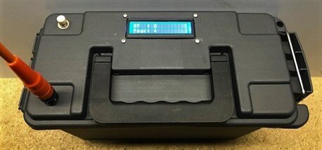
The Phase 1 plan is to verify my ability to measure RF signals using a dipole antenna.  I have built a few iterations of RF Field Strength detectors.  See Field Strength Meter for an example of how they are put together.


With the field strength meters working, it was time to get a recurring transmitter set up so the meters had something to receive.  This would also allow me to sort of calibrate them.  This was supposed to be the easy part.  Silly me.

imageimageimageimage


I opted for an Arduino controlled automated transmitter setup that amateur radio folks call a "fox".  It is used in hidden transmitter hunts using different radio direction finding techniques.  Mine would do a tune and give my call sign in Morse code.  Only...

1.  I decided to use some of my Arduino Mini's.  Not the Mini Pro.  I had to relearn that the Mini gets programmed as a Nano - using the Old Bootloader.  Slight delay.

2.  My radio cable didn't seem to work.  Get a new one.  The new one doesn't work.  Try a different radio.  That one sometimes works.  The "key the mic" relay works but the radio circuit doesn't trigger reliably.  It takes a lot of fiddling with.

3.  Let the magic smoke out of a Mini by holding down the reset button too long.  Get another Mini and start over.

*  The root of my issue seems to be in my cheap Baofeng radios.  The Arduino part is working fine.

4.  Take a radio apart trying to see if I can direct wire to it.  Break the radio.  Order repair part.  Buy different cheap radio.


Update:  Receive new cheap radio.  It doesn't respond to the relay that is supposed to key the transmitter either.  Setting this part of the project to the side for now.  Go to Plan B:  Key the mic by hand.


Update 30 DEC 2019:  I have healed the fox.  The schematic from the Internet was wrong.  Imagine that.  I used the information from Whitecourt Amateur Radio (Fox Hunt Transmitter – Whitecourt Amateur Radio) but have provided the corrected schematic - and a picture of the Arduino setup that will soon reside in one of the plastic ammo boxes I have.  It's a shame that I killed a $40 radio in the process.  Still... I got to take it apart and see what's inside.  I guess I'll never grow up that way.  Arduino Mini RDF Fox

imageimage


The next step was to attempt to somewhat calibrate the DMM meters to each other and the Arduino meters to each other.  After much trying, I abandoned this idea.  To get as consistent measurements as possible, I'll stick to one meter.

During this process, I had an antenna concept reinforced.  It's called "Take Off Angle".  The field strength can vary quite a bit (in the near field) over a few inches of elevation - meaning at which height I held the meter.

So... the field strength meter in the plastic ammo box is destined to be re-purposed.


On to the testing!

You don't have permission to edit metadata of this video.
Edit media
x
image
Upload Preview
image
image

This is the 2 meter dipole antenna I used.  It is vertically polarized and the feed line is run horizontally out from the feed point to decrease the SWR (Standing Wave Ratio).  If the feed line is allowed to just hang, it increases the SWR or reflected power in the antenna.  The white post in front of the base/bucket is to attach the string that insures I stay at the correct distance when making measurements.  I have included the video.  Thankfully, it got up to 0C that day.

I tested the field strength a half a dozen times before the weather drove me back indoors.  By reviewing the aggregate readings, I determined that the radiation pattern for this dipole was the one below.

image

I used a radar plot because the distance scaling was easier to use.  The view is top down.  The antenna feed point is the center of the circle and the feed line extends from the center toward the 180 degree mark.

This plot revealed some interesting characteristics of my dipole antenna.

1.  It is not omnidirectional.  The radiation pattern favors an opposite feed line direction.  A vertical dipole is supposed to have a uniformly circular radiation pattern.

2.  The feed line side of the horizontal support has a slightly weaker signal than the non-feed line side.

Both of these phenomenon point to the feed line influencing the radiation pattern.  Even with a common mode choke on the feed line, it still has influence.

My opinion is that the feed line is also broadcasting RF, resulting in a more directional pattern than expected.


Even with this less than perfect radiation pattern, I have still verified my ability to measure relative RF field strength.  Phase 2 will be to verify the radiation pattern of a three element Yagi antenna and to attempt to measure the nulls.

Phase 2:Antenna Radiation - Phase 2

  • Sign in to reply

Top Comments

  • shabaz
    shabaz over 5 years ago +4
    Hi Mike, This is a nice experiment. I think it's one of those experiments that a lot of people don't try, thinking that the results will be too unpredictable, but you've shown it is possible to get quite…
  • kmikemoo
    kmikemoo over 5 years ago in reply to shabaz +3
    shabaz Thank you. You are correct that the readings are unpredictable. I took a bunch of them - enough to see the pattern. If I had hair, I would have pulled it all out. A smarter man would have probably…
  • 14rhb
    14rhb over 5 years ago +1
    Hi Mike, I congratulate you on your tenacity to continue taking multiple measurements in such conditions, it seems to have paid off though as your polar plot looks very credible. Please keep your RF blogs…
Parents
  • shabaz
    shabaz over 5 years ago

    Hi Mike,


    This is a nice experiment. I think it's one of those experiments that a lot of people don't try, thinking that the results will be too unpredictable, but you've shown it is possible to get quite clean results through multiple readings to plot, even detecting the anomaly which as you say could be related to the coax.

    Is this the 2m band? Or some UHF band?

    • Cancel
    • Vote Up +4 Vote Down
    • Sign in to reply
    • More
    • Cancel
Comment
  • shabaz
    shabaz over 5 years ago

    Hi Mike,


    This is a nice experiment. I think it's one of those experiments that a lot of people don't try, thinking that the results will be too unpredictable, but you've shown it is possible to get quite clean results through multiple readings to plot, even detecting the anomaly which as you say could be related to the coax.

    Is this the 2m band? Or some UHF band?

    • Cancel
    • Vote Up +4 Vote Down
    • Sign in to reply
    • More
    • Cancel
Children
  • kmikemoo
    kmikemoo over 5 years ago in reply to shabaz

    shabaz Thank you.  You are correct that the readings are unpredictable.  I took a bunch of them - enough to see the pattern.  If I had hair, I would have pulled it all out.  A smarter man would have probably quit.  I'm not that man. image

    The Yagi and the cardioid are being just as problematic.


    The experiment is using the 2m band.  I had considered using the 70cm band but there is so little activity on it in my area that I would not get any real use out of the antennas afterwards.  By going with 2m, I can use the antennas and what I've learned in my local amateur radio club.  The dipole is actually designed to be disassembled and fit in a speaker stand bag.  The horizontal feed line support and the vertical main support are threaded PVC and the whole system can be erected in just a couple of minutes.  I hope to use it to spark more interest in the hobby and to encourage new Hams to build an antenna.

    imageimage

    • Cancel
    • Vote Up +3 Vote Down
    • Sign in to reply
    • More
    • Cancel
element14 Community

element14 is the first online community specifically for engineers. Connect with your peers and get expert answers to your questions.

  • Members
  • Learn
  • Technologies
  • Challenges & Projects
  • Products
  • Store
  • About Us
  • Feedback & Support
  • FAQs
  • Terms of Use
  • Privacy Policy
  • Legal and Copyright Notices
  • Sitemap
  • Cookies

An Avnet Company © 2025 Premier Farnell Limited. All Rights Reserved.

Premier Farnell Ltd, registered in England and Wales (no 00876412), registered office: Farnell House, Forge Lane, Leeds LS12 2NE.

ICP 备案号 10220084.

Follow element14

  • X
  • Facebook
  • linkedin
  • YouTube