


The Quantenkompassinator is an over-engineered motorized compass. Built around a Digilent Arty S7 50 board with an AMD Xilinx Spartan-7 FPGA. It is a differential drive mobile robot with PID control that always points in the same direction using Memsic's MMC34160PJ magnetometer, two DC motors and rotational positon and speed feedback with hall effect magnetic sensors.
What is it for? According to our empirical tests, the Quantenkompassinator compass allows us to locate quantum portals inside a house. See demo video:
The Quantenkompassinator is a stubborn robot who is determined to always face south. Why south? Very simple, it is very vain and likes to look handsome in the videos.
The following video shows its stubbornness.
System description
The system is composed by a differential wheeled robot and a magnetometer.
A differential wheeled robot is a mobile robot whose movement is based on two separately driven wheels placed on either side of the robot body. It can thus change its direction by varying the relative rate of rotation of its wheels and hence does not require an additional steering motion. When the two wheels spin in opposite directions because the two wheels are constrained by the physical mechanism to remain in a fixed geometric relationship to one another, these opposite but equal forward wheel speeds cause the robot to rotate, with both wheels velocities tangent to a circle of diameter centered at the origin of the body-attached frame.
System parts:
- A magnetometer
- A small OLED display
- A motor driver board with 2 H-bridges
- Two DC motors
- A Microblaze soft processor
- PWM motor controller

The horizontally positioned magnetometer informs the robot of its orientation. The robot continuously tries to orient the sensor at 0 degrees, towards North by turning the robot along the shortest path.
The turns are made by moving one wheel in one direction and the other in the opposite direction using PWM signals controlled by a PID control system, keeping the center of the robot at the same point, without moving, just rotating.
Four magnetic Hall sensors and two disks with small magnets attached to the shafts of the DC motors give feedback of the position and angular speed of the wheels.
The desired effect is that the robot simulates the movement of the arrow of a classic magnetic compass.
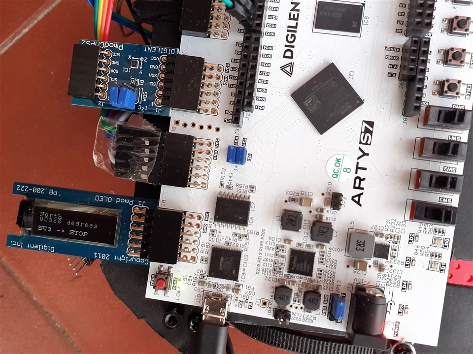
The OLED display is attached to JA Pmod connector and the Pmod CMPS2 compass sensor is attached to the JC Pmod connector on the Digilent Arty S7 board.
North direction on the board is opposite to the arrow direction. The arrow is pointing to the South in the following image.

Bill of materials
If you want to replicate this project you will need:
| Product Name | Manufacturer | Datasheet |
| Arty S7 50 | Digilent | Buy Now |
| TI-RSLK | element14 | Buy Now |
| PmodOLED | Digilent | Buy Now |
| PmodCMPS | Digilent | Buy Now |
Pmod CMPS2 : 3-Axis Compass sensor
The Digilent Pmod CMPS2 is a digital compass module using Memsic's MMC34160PJ magnetometer. The local magnetic field strength can be measured in a ±16 Gauss range with a heading accuracy of 1° and up to 0.5 mG of resolution.
| {gallery}Digilent Pmod CMPS2 |
|---|
|
|
|
|
 |


References
Digilent PmodOLED
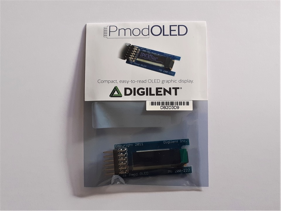
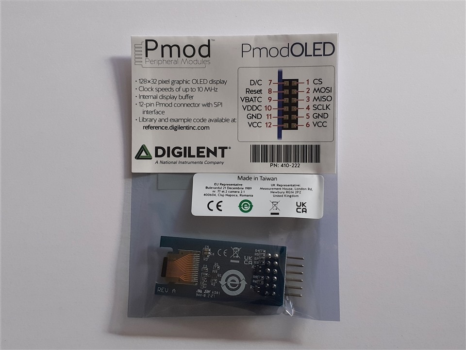
The Digilent Pmod OLED (Revision A) is an organic LED module with a 128×32 pixel display. Primary IC SSD1306

References:
| {gallery}Digilent PmodOLED |
|---|
|
Digilent PmodOLED unboxing |
|
Digilent PmodOLED unboxing |
|
Digilent PmodOLED Front |
|
Digilent PmodOLED Back |


The OLED display is attached to JA Pmod connector and the Pmod CMPS2 compass sensor is attached to the JC Pmod connector on the Digilent Arty S7 board.
Robot Chassis
The robot is built using the Pololu Romi chassis, is a differential-drive mobile robot platform with a diameter of 6.5″ (165 mm) and an integrated battery holder for six AA batteries. The drive wheels are located on a diameter of the circular base plate, allowing for turns or spinning in place. A large, fixed ball caster in the rear provides a smooth third point of contact.

Reference: Pololu - Romi Chassis Kit - Red
Motor driver and power distribution board
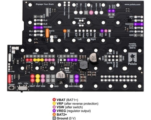
The robot uses the Pololu Motor Driver and Power Distribution Board for Romi Chassis. This motor driver and power distribution board is designed specifically for the Romi chassis as a convenient way to drive the chassis' motors and power the rest of the electronics that make up your robot. It features two DRV8838 motor drivers, one for each of the chassis' motors, and a powerful switching step-down regulator that can supply a continuous 2.5 A at 5 V or 3.3 V.
The output driver block consists of Nchannel power MOSFETs configured as an H-bridge to drive the motor winding. An internal charge pump generates needed gate drive voltages.
Reference: Pololu - Motor Driver and Power Distribution Board for Romi Chassis
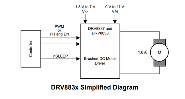
DRV8838 Low-Voltage H-Bridge Driver
The DRV8838 on the Motor Driver and Power Distribution Board is an H-bridge driver that can drive one dc motor or other devices like solenoids. The outputs are controlled using a PH-EN interface. It includes a low-power sleep mode, which can be enabled using the nSLEEP pin. It integrates the necessary driver FETs and FET control circuitry into a single device. In addition, it adds protection features beyond traditional discrete implementations: undervoltage lockout, overcurrent protection, and thermal shutdown.
Reference: DRV8838 data sheet, product information and support | TI.com
H-Bridge Control
The DRV8838 is controlled using a PHASE/ENABLE interface. This interface uses one pin to control the H-Bridge current direction, and one pin to enable or disable the H-Bridge.
Logic table for the DRV8838
| nSLEEP | PH | EN | OUT1 | OUT2 | FUNCTION (DC Motor) |
| 0 | X | X | Z | Z | Coast |
| 1 | X | 0 | L | L | Brake |
| 1 | 1 | 1 | L | H | Reverse |
| 1 | 0 | 1 | H | L | Forward |
Reference:
DRV883x Low-Voltage H-Bridge Driver datasheet (Rev. F) (ti.com)
Motor Driver and Power Distribution Board Modifications
To configure the Motor Driver and Power Distribution Board (MDPDB), we need to set the logic levels of the Motor Driver board to the logic levels used in the GPIOs of the Arty S7 board.
Follow these steps to configure the motor driver board for the robot:
- Cut the VPU—VREG jumper on the MDPDB
- Cut the VCCMD—VREG jumper on the MDPDB
- Connect a ground wire from the MDPDB to ground on the Arty S7
- Connect VREG (+5V) from the MDPDB to +5V VCC5V0 on the Arty S7
- Connect VPU from the MDPDB to 3.3V VCC on the Arty S7. Use VCC form a PMOD header
- Connect VCCMD from the MDPDB to 3.3V VCC on the Arty S7. Use VCC form a PMOD header
We can power the Arty S7 board through the VCC5V0 pin (JP13 power select)
Connect VREG (+5V) from the MDPDB to +5V VCC5V0 on the Arty S7

Powering the Arty S7 with the Power Distribution Board

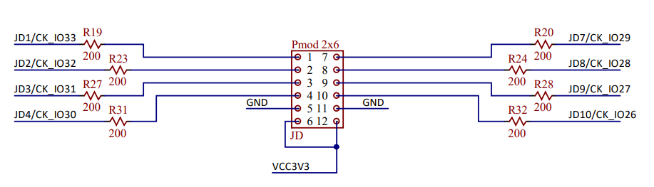
For the reference logic levels we can use the two VCC3V3 (3.3V) outputs from an unused PMOD connector.

Initially we used this configuration but sometimes when starting the motors the Arty S7 board restarts, so we are definitely powering the Arty S7 board through the USB port using a Powerbank, so the power of the chassis batteries is exclusively for the motors.
Reference: arty_s7_sch-rev_b.pdf(digilent.com)
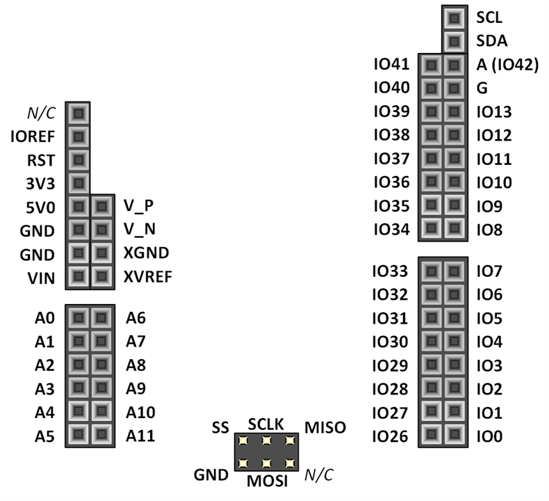
Arduino/chipKIT Shield Connector
We will design the PWM, DIR, nSLEEP outputs connected to the standard Arduino and chipKIT shield of the Arty S7. The shield connector has 45 pins connected to the FPGA for general purpose Digital I/O. It is possible to use these pins for just about anything including digital read/write, SPI connections, UART connections, I2C connections, and PWM.
Six of these pins (labeled AN0-AN5) can also be used as single-ended analog inputs with an input range of 0V-3.3V, and another four (labeled AN6-9) can be used as differential analog input pairs with an input range of 0V-1.0V.
The Arty S7's shield connector is implemented on headers J1, J2, J3, J5, J6, and J8.
| MDPDB | Arty S7 |
| PWM Right | IO0 |
| DIR Right | IO1 |
| nSLEEP Right | IO2 |
| PWM Left | IO3 |
| DIR Left | IO4 |
| nSLEEP Left | IO5 |
nSLEEP signals are no used, but reserved for future uses.
Pulse Width Modulation
We will use PWM to control the speed of the two motors. Pulse Width Modulation (PWM) control or Pulse Duration Modulation (PDM) is a very ingenious method used to control the average power delivered by an electrical signal to a load, by effectively chopping it up into discrete parts. It is a method that is very easy to implement and has high efficiency. The PWM signal is essentially a high frequency (typically greater than 1KHz) square wave. The duty cycle of this square wave is varied to vary the power supplied to the load. The main uses of PWM, but not limited to these, are power delivery control, voltage regulation, audio effects and amplification, dimming lights, modulation of signals in telecommunications, control of motor rotation angle in servomotors.

Motor speed control with PWM
The electrical power (P) delivered to the motor is the product of voltage (V), current (C) and duty cycle.
P = V * I * duty
Depending of the polarity of the current and voltage the motors can spin forward or backward.
The motor converts electrical power into mechanical power that delivers torque causing the wheel to spin. Torque is force * distance.
We will fix the voltage and the current will depend on the friction caused by the mechanical load.
Reference: Pulse-width modulation - Wikipedia
AXI Timer/Counter Intellectual Property (IP)
There are many ways to generate a PWM signal with FPGA. We will use the simplest way a preconfigured IP block. The AXI Timer/Counter is a 32-bit timer module that attaches to the AXI4-Lite interface. In Cascade mode, it can be used as 64-bit timer module. This Xilinx® LogiCORE IP module is provided at no additional cost with the Xilinx Vivado® Design Suite.
Control System
We want to build a control system for our robot. With a control system, we can independently set the rotation speed of each motor. The control system measures speed and uses feedback to adjust the PWM duty cycle of each motor to achieve the desired speed. With the control system, the robot can move in a straight line, run at a desired speed, travel a prescribed distance, or turn at a prescribed angle.
Tachometer
A tachometer is a sensor with digital outputs that relate to rotational speed.
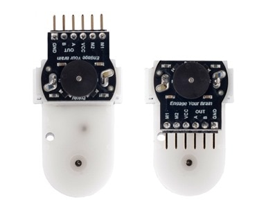
Hall Effect Magnetic Quadrature Encoder
We use the Pololu - Romi Encoder Pair Kit. These quadrature encoders use a magnetic disc and Hall effect sensors to provide 12 counts per revolution of the motor shaft.
The motors used on the Romi have a 120:1 gear reduction and the encoders are connected directly to the motor output shaft and have 12 Counts Per Revolution (CPR). With the provided gear ratio, this nets 1440 counts per wheel revolution. We will use only one sensor output and will count only rising edges so each output pulses 360 times per rotation. If we measure the Period (in sec) of one of the tachometer signals, we can calculate the motor Speed in rpm as
Speed = 360*60/Period
The sensors operate from 3.5 V to 18 V and provide digital outputs. The outputs (ELA, ELB, ERA, ERB) are pull up to VPU 3V3 from the Arty S7 board.

Differential Motors Position Module.
We have designed a Differential Motors Position Module.
This module that allow us to:
- Get Speeds : Measure current angular speeds of motor1 and motor2 (in RPM) and store them in motor speed.
- Get Distance Traveled: Return mean distance traveled by motor1 and motor2
- Get Edge Counts: Get sensor and clock edge counts of each motor for computing speed
- Clear Speed Counters: Clear the registers storing counts of sensor and clock edges for computing speed
- Get Motor Positions: Get current positions of the two motors
- Get Position Difference: Get current position difference between motor1 and motor2
- Clear Position Counters: Clear the cumulative position counters for both motors
The design on the FPGA allow us to increment the counters in parallel and not lose any increments and also get the difference of two counters at the same time.
The module has three inputs. Two inputs for the motor sensors and another input to clear the control counters.
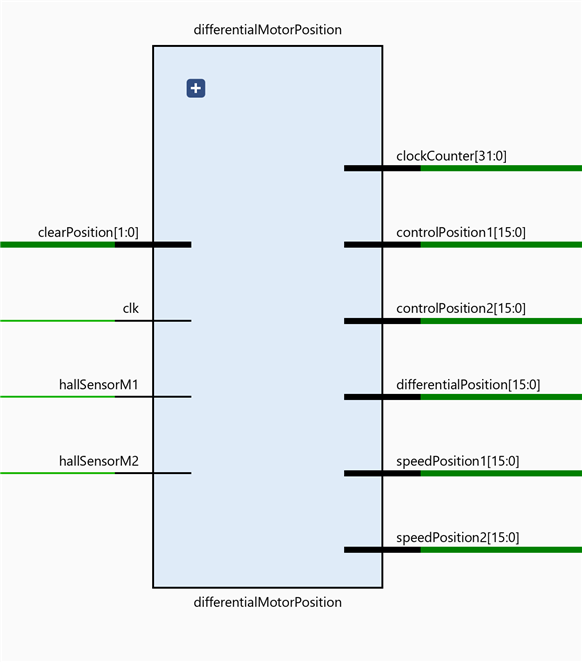
Inputs
- clk: Clock
- hallSensorM1: Sensor input signal from the encoder of motor 1
- hallSensorM2: Sensor input signal from the encoder of motor 2
- clearPosition: Signal for resetting position counters, controlPosition1 and/or controlPosition2
Outputs
- speedPosition1: Counter for speed calculation relative to the motor1
- controlPosition1 : Counter for position control relative to the motor1
- speedPosition2: Counter for speed calculation relative to the motor2
- controlPosition2: Counter for position control relative to the motor1
- differentialPosition: position difference between motor1 and motor2
- clockCounter: Clock pulse counter.
This module will use two Motor Position Counter modules to keep track of the individual counters of each motor.
Motor Position Counter Module
For each DC motor we have a separate module that keeps track of the counters.
It keeps track of two counters, one for position calculation and one for velocity calculation.

Inputs
- clk: clock
- hallSensor: hall sensor input signal
- clearPosition: clearPosition[0] clears position1, // clearPosition[2] clears position2
- subtractDistance: substract distance from controlPosition
- distance: distance amount to subtract from controlPosition
Outputs
- speedPosition: for speed calculation
- controlPosition: for position control
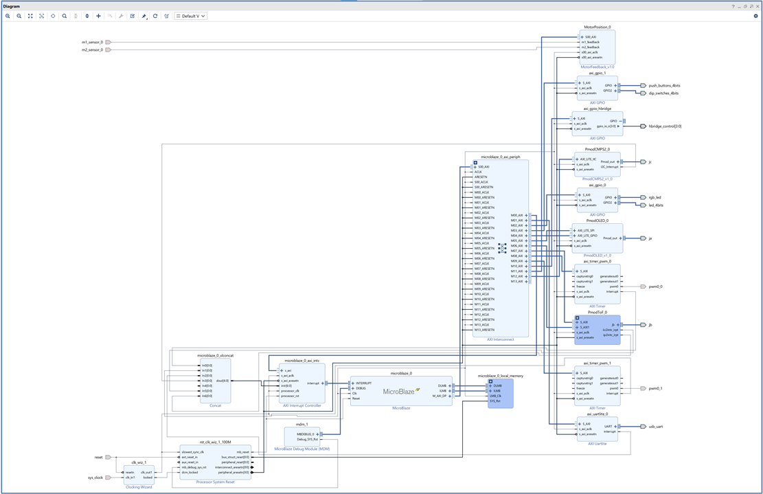
FPGA Hardware Block Design
The hardware design has been built around the MicroBlaze soft processor.
Software Application
Once all the hardware abstraction layers have been created, the application is very simple.
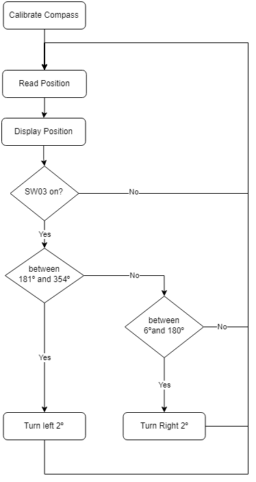
First there is a calibration stage in which the robot rotates in left and right directions while sampling the strength of the magnetic field. After the calibration period, if the switch sw03 is on, the robot rotates in order to leave the orientation at 0 degrees (between 6º and -6º). When it achieves the objective, it stops. If the switch sw03 is going to be measuring and showing the data on the display but without moving the robot.
Source code
You can download the libraries with the drivers and the hardware abstraction layer from the github repository.
/******************************************************************************/
/*                                                                            */
/* compass_app.c -- Differential robot compass app                            */
/*                                                                            */
/******************************************************************************/
/* Author: Enrique Albertos                                                   */
/*                                                                            */
/******************************************************************************/
/* File Description:                                                          */
/* Over-engineered motorized compass made with a FPGA based differential      */
/* drive mobile robot with PID control that always points in the same         */
/* direction using Memsic's MMC34160PJ magnetometer, two DC motors and        */
/* rotational positon and speed feedback with hall effect magnetic sensors.   */
/******************************************************************************/
/* Revision History:                                                          */
/*                                                                            */
/*    06/08/2022 :   Created                                                  */
/*                                                                            */
/******************************************************************************/

#include "compass_app.h"

int compass_app(void);
void CompassInitialize();
int readOrientation(CMPS2_DataPacket* data, PmodCMPS2* myDevice,
		CMPS2_CalibrationData* myCalibrationData, const int myDeclination,
		char** cardinal, char* cardinal_table[]);

void displayOrientation(BotDrivers* botDrivers, int deg, char* cardinal);

PmodCMPS2 myDevice;
CMPS2_CalibrationData myCalibrationData;

const int myDeclination = 1; // Magnetic declination for Zaragoza, Spain: +0.85° (1°51')

const u8 chip_address = 0x30; // I2C chip address

BotDrivers botDrivers;

int compass_app(void) {
	CompassInitialize();
	CompassRun();
	return 0;
}

void CompassRun() {
	char *cardinal_table[] = { "North", "North East", "East", "South East",
			"South", "South West", "West", "North West" };
	char *cardinal;
	int deg;
	CMPS2_DataPacket data;

	CompassClearCalibration(&myCalibrationData);
	OLED_SetCharUpdate(&botDrivers.oled, 0);
	OLED_ClearBuffer(&botDrivers.oled);
	OLED_SetCursor(&botDrivers.oled, 0, 0);
	OLED_PutString(&botDrivers.oled, "   MOTORIZED");
	OLED_SetCursor(&botDrivers.oled, 0, 1);
	OLED_PutString(&botDrivers.oled, "  COMPASS v1.0");
	OLED_SetCursor(&botDrivers.oled, 0, 3);
	OLED_PutString(&botDrivers.oled, "SW3 -> RUN");
	OLED_Update(&botDrivers.oled);
	while (!SWITCHES_DRIVER_poll_switch4(&botDrivers.switchesDriver)) {
	}

	sleep(1);

	for (int i = 0; i < 270; i += 6) {
		DRIVING_DRIVER_turn_left_continuous_degrees(&botDrivers.drivingDriver,
				6);
		deg = readOrientation(&data, &myDevice, &myCalibrationData,
				myDeclination, &cardinal, cardinal_table);
		xil_printf("Degree: %d;  Y Direction: %s\r\n", deg, cardinal);

	}
	DRIVING_DRIVER_delay_until_stop(&botDrivers.drivingDriver);
	for (int i = 0; i < 270; i += 6) {
		DRIVING_DRIVER_turn_right_continuous_degrees(&botDrivers.drivingDriver,
				6);
		deg = readOrientation(&data, &myDevice, &myCalibrationData,
				myDeclination, &cardinal, cardinal_table);
		xil_printf("Degree: %d;  Y Direction: %s\r\n", deg, cardinal);

	}
	DRIVING_DRIVER_delay_until_stop(&botDrivers.drivingDriver);

	while (1) {
		if (SWITCHES_DRIVER_poll_switch4(&botDrivers.switchesDriver)) {
			deg = readOrientation(&data, &myDevice, &myCalibrationData,
					myDeclination, &cardinal, cardinal_table);

			xil_printf("Degree: %d;  Y Direction: %s\r\n", deg, cardinal);
			if (deg > 180 && deg < 354) {
				xil_printf("turn left: %d\r\n", 360 - deg);
				while (deg > 180 && deg < 354) {
					DRIVING_DRIVER_turn_right_continuous_degrees(
							&botDrivers.drivingDriver, 2);
					deg = readOrientation(&data, &myDevice, &myCalibrationData,
							myDeclination, &cardinal, cardinal_table);
					displayOrientation(&botDrivers, deg, cardinal);
				}
				xil_printf("turn left: %d\r\n", 360 - deg);
			} else if (deg > 6 && deg <= 180) {
				while (deg > 6 && deg <= 180) {
					DRIVING_DRIVER_turn_left_continuous_degrees(
							&botDrivers.drivingDriver, 2);
					deg = readOrientation(&data, &myDevice, &myCalibrationData,
							myDeclination, &cardinal, cardinal_table);
					displayOrientation(&botDrivers, deg, cardinal);
				}
				xil_printf("turn right: %d\r\n", deg);
			}

		} else {
			deg = readOrientation(&data, &myDevice, &myCalibrationData,
					myDeclination, &cardinal, cardinal_table);
		}
		displayOrientation(&botDrivers, deg, cardinal);
	}
}

void CompassInitialize() {

	CMPS2_begin(&myDevice, XPAR_PMODCMPS2_0_AXI_LITE_IIC_BASEADDR,
			chip_address);
	usleep(10000);
	CMPS2_SetSensor(&myDevice);
	usleep(10000);
	CMPS2_SetOutputResolution(&myDevice, 0b00);

	xil_printf("COMPASS application Started\r\n");

	BOT_init(&botDrivers);

}

int readOrientation(CMPS2_DataPacket* data, PmodCMPS2* myDevice,
		CMPS2_CalibrationData* myCalibrationData, const int myDeclination,
		char** cardinal, char* cardinal_table[]) {

	int deg;
	*data = CMPS2_GetData(&*myDevice);
	CompassCalibrate(&*myDevice, &*myCalibrationData, *data);
	deg = CompassConvertDegree(&*myDevice, *myCalibrationData, *data,
			myDeclination);
	*cardinal = CompassGetCardinalDirectionString(deg, cardinal_table);
	return deg;
}

void displayOrientation(BotDrivers* botDrivers, int deg, char* cardinal) {
	OLED_SetCharUpdate(&botDrivers->oled, 0);
	OLED_ClearBuffer(&botDrivers->oled);
	OLED_SetCursor(&botDrivers->oled, 0, 0);
	OLED_PutString(&botDrivers->oled, cardinal);
	OLED_SetCursor(&botDrivers->oled, 0, 1);
	OLED_putIntVariable(&botDrivers->oled, deg);
	OLED_PutString(&botDrivers->oled, " degrees");
	OLED_SetCursor(&botDrivers->oled, 0, 3);
	OLED_PutString(&botDrivers->oled, "SW3 -> STOP");
	OLED_Update(&botDrivers->oled);
}

int CompassConvertDegree(PmodCMPS2 *InstancePtr, CMPS2_CalibrationData calib,
		CMPS2_DataPacket data, int declination) {
	int tx, ty;
	int deg;

	if (data.x < calib.mid.x)
		tx = (calib.mid.x - data.x);
	else
		tx = (data.x - calib.mid.x);

	if (data.y < calib.mid.y)
		ty = (calib.mid.y - data.y);
	else
		ty = (data.y - calib.mid.y);

	if (data.x < calib.mid.x) {
		if (data.y > calib.mid.y)
			deg = 90 - atan2f(ty, tx) * 180 / 3.14159;
		else
			deg = 90 + atan2f(ty, tx) * 180 / 3.14159;
	} else {
		if (data.y < calib.mid.y)
			deg = 270 - atan2f(ty, tx) * 180 / 3.14159;
		else
			deg = 270 + atan2f(ty, tx) * 180 / 3.14159;
	}

	deg += declination;

	while (deg >= 360)
		deg -= 360;
	while (deg < 0)
		deg += 360;

	return deg;
}

void CompassClearCalibration(CMPS2_CalibrationData *calib) {
	calib->max.x = 0x8000; // Center point of 0x0000 -> 0xFFFF
	calib->max.y = 0x8000;
	calib->max.z = 0x8000;
	calib->min.x = 0x8000;
	calib->min.y = 0x8000;
	calib->min.z = 0x8000;
	calib->mid.x = 0x8000;
	calib->mid.y = 0x8000;
	calib->mid.z = 0x8000;
}

void CompassCalibrate(PmodCMPS2 *InstancePtr, CMPS2_CalibrationData *calib,
		CMPS2_DataPacket data) {
	if (data.x > calib->max.x)
		calib->max.x = data.x; // Track maximum / minimum
	if (data.y > calib->max.y)
		calib->max.y = data.y; // value seen per axis
	if (data.z > calib->max.z)
		calib->max.z = data.z;
	if (data.x < calib->min.x)
		calib->min.x = data.x;
	if (data.y < calib->min.y)
		calib->min.y = data.y;
	if (data.z < calib->min.z)
		calib->min.z = data.z;
	calib->mid.x = (calib->max.x >> 1) + (calib->min.x >> 1); // Find average
	calib->mid.y = (calib->max.y >> 1) + (calib->min.y >> 1);
	calib->mid.z = (calib->max.z >> 1) + (calib->min.z >> 1);
}

char *CompassGetCardinalDirectionString(int deg, char *cardinal_table[]) {
	float fdeg = deg;
	if (fdeg > 337.5)
		fdeg -= 337.5;
	else
		fdeg += 22.5;
	fdeg /= 45.0;
	return cardinal_table[(int) fdeg];
}
Conclusion
It has been a very fun project. We have taken advantage of everything we have learned in the last two months about FPGAs by participating in element14's "7 Ways to Leave Your Spartan-6" program. You can see the summary with everything we learned in "7 Ways to Leave Your Spartan-6 FPGA" program. My summary. - Blog - FPGA - element14 Community
Top Comments
-

Andrew J
-
Cancel
-
Vote Up
0
Vote Down
-
-
Sign in to reply
-
More
-
Cancel
Comment-

Andrew J
-
Cancel
-
Vote Up
0
Vote Down
-
-
Sign in to reply
-
More
-
Cancel
Children