 | Enter Your Electronics & Design Project for a chance to win a $200 shopping cart! Submit an EntrySubmit an Entry Back to homepage | Project14 Home |
| Monthly Themes | ||
| Monthly Theme Poll |
Hello Everyone,My name is Harji Nagi.I am currently a third year student studying electronics and communication engineering from Pranveer Singh Institute Of Technology,Kanpur(UP).I have a keen interest in robotics,arduino,Artificial Intelligence and Analog electronics.The word “gimbal” is defined as a pivoted support that allows rotation of any object in a single axis. So a three-axis gimbal allows any object mounted on the gimbal to be independent of the movement of the one holding the gimbal. The gimbal dictates the movement of the object, not the one carrying it.It consists of 3 MG995 servo motors for the 3-axis control, and a base on which the MPU6050 sensor, the Arduino and the battery will be placed.It’s used to keep the camera stabilized with no vibration. A 3-axis gimbal ensures that the motion of the camera is stabilized even if the one holding it is going up and down, left and right, front and back. This is what we refer to as yaw, pitch, and roll stabilization.
Step 1: Components List
The component list are:
1)Arduino Uno
2)8V,1.5 Amp Battery for powering Arduino Uno
3) 7805 Voltage regulator Ic or you can use buck conveter
4)MPU 6050
5)3*(MG995 SERVO Motors)
6)Jumper Wires
Other Equipments:
1)Soldering Iron
2)Glue Gun
3)Drill machine
4)Food Can
Instead of using breadborad I have use small coustom perf board for positive and negative bus connection.
Step 2: Assembling
Foamcore, foam board, or paper-faced foam board is a lightweight and easily cut material used for mounting Servo motor and for making scale models.
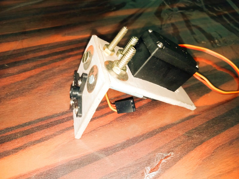
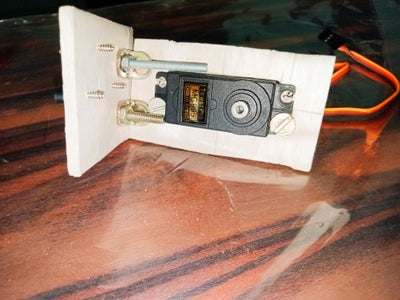
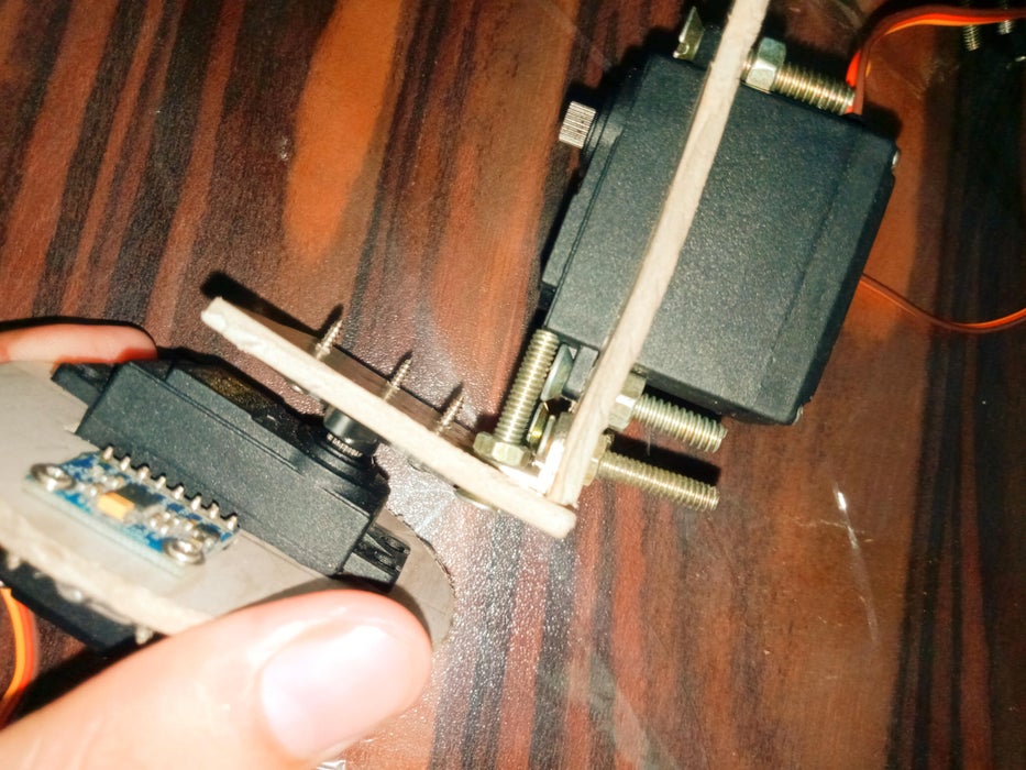
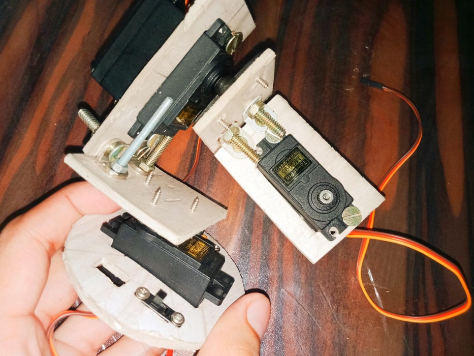
Firstly I made a DIY L-shape brackets to mount servo motor with the help of foam board.
Step 3:
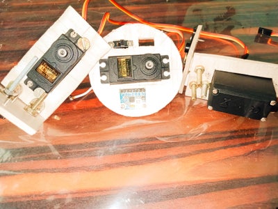
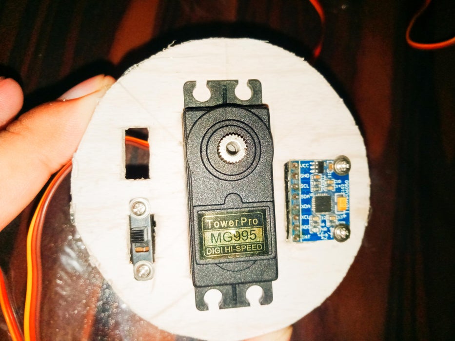
Assembling the gimbal was quite easy. I started with installing the Yaw servo,MPU 6050 sensor and ON-OFF switch. Using bolts and nuts I secured it to the base
Step 4: Next, Using the Same Method I Secured the Roll Servo. the Parts Are Specifically Designed to Easily Fit the MG995 Servos
Step 5: Next, Using the Same Method I Secured the Roll Servo. the Parts Are Specifically Designed to Easily Fit the MG995 Servos
Step 6: Connections
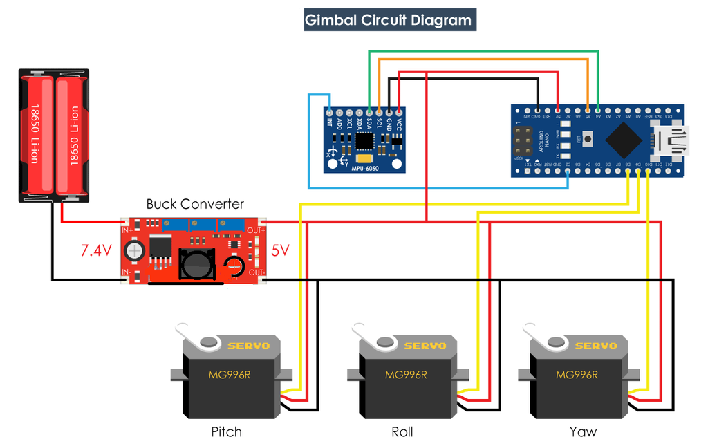
In the circuit diagram you can use either buck converter or 7805 Voltage regulator IC to convert 8V to 5 V.The microcontroller which is given the circuit diagram is Arduino Nano you can also use Arduino Uno,Arduino Mega.
The SCL and SDA pins of MPU 6050 is connected to Arduino Analog pin A5 and A4.(SCL and SDA pin may vary so check out datasheet for SCl and SDA pins for other microcontroller)
Step 7: Connection With 7805 Voltage Regulator IC
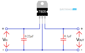
This circuit diagram is for the connection of 7805 voltage regulator ic, connect the 8v battery at Vin and you will get an output voltage of 5v.
Step 8: Coding
You must include the following libraries:
1)#include<Wire.h>Click Hereto download zip file
2)#include<Servo.h>Click Here to download zip file
After downloading the zip file,add zip library in arduino sketch
For Code
- /*
- DIY Gimbal - MPU6050 Arduino Tutorial
- Code based on the MPU6050_DMP6 example from the i2cdevlib library by Jeff Rowberg:
- https://github.com/jrowberg/i2cdevlib
- */
- // I2Cdev and MPU6050 must be installed as libraries, or else the .cpp/.h files
- // for both classes must be in the include path of your project
- #include "I2Cdev.h"
- #include "MPU6050_6Axis_MotionApps20.h"
- //#include "MPU6050.h" // not necessary if using MotionApps include file
- // Arduino Wire library is required if I2Cdev I2CDEV_ARDUINO_WIRE implementation
- // is used in I2Cdev.h
- #if I2CDEV_IMPLEMENTATION == I2CDEV_ARDUINO_WIRE
- #include "Wire.h"
- #endif
- #include <Servo.h>
- // class default I2C address is 0x68
- // specific I2C addresses may be passed as a parameter here
- // AD0 low = 0x68 (default for SparkFun breakout and InvenSense evaluation board)
- // AD0 high = 0x69
- MPU6050 mpu;
- //MPU6050 mpu(0x69); // <-- use for AD0 high
- // Define the 3 servo motors
- Servo servo0;
- Servo servo1;
- Servo servo2;
- float correct;
- int j = 0;
- #define OUTPUT_READABLE_YAWPITCHROLL
- #define INTERRUPT_PIN 2 // use pin 2 on Arduino Uno & most boards
- bool blinkState = false;
- // MPU control/status vars
- bool dmpReady = false; // set true if DMP init was successful
- uint8_t mpuIntStatus; // holds actual interrupt status byte from MPU
- uint8_t devStatus; // return status after each device operation (0 = success, !0 = error)
- uint16_t packetSize; // expected DMP packet size (default is 42 bytes)
- uint16_t fifoCount; // count of all bytes currently in FIFO
- uint8_t fifoBuffer[64]; // FIFO storage buffer
- // orientation/motion vars
- Quaternion q; // [w, x, y, z] quaternion container
- VectorInt16 aa; // [x, y, z] accel sensor measurements
- VectorInt16 aaReal; // [x, y, z] gravity-free accel sensor measurements
- VectorInt16 aaWorld; // [x, y, z] world-frame accel sensor measurements
- VectorFloat gravity; // [x, y, z] gravity vector
- float euler[3]; // [psi, theta, phi] Euler angle container
- float ypr[3]; // [yaw, pitch, roll] yaw/pitch/roll container and gravity vector
- // packet structure for InvenSense teapot demo
- uint8_t teapotPacket[14] = { '$', 0x02, 0, 0, 0, 0, 0, 0, 0, 0, 0x00, 0x00, '\r', '\n' };
- // ================================================================
- // === INTERRUPT DETECTION ROUTINE ===
- // ================================================================
- volatile bool mpuInterrupt = false; // indicates whether MPU interrupt pin has gone high
- void dmpDataReady() {
- mpuInterrupt = true;
- }
- // ================================================================
- // === INITIAL SETUP ===
- // ================================================================
- void setup() {
- // join I2C bus (I2Cdev library doesn't do this automatically)
- #if I2CDEV_IMPLEMENTATION == I2CDEV_ARDUINO_WIRE
- Wire.begin();
- Wire.setClock(400000); // 400kHz I2C clock. Comment this line if having compilation difficulties
- #elif I2CDEV_IMPLEMENTATION == I2CDEV_BUILTIN_FASTWIRE
- Fastwire::setup(400, true);
- #endif
- // initialize serial communication
- // (115200 chosen because it is required for Teapot Demo output, but it's
- // really up to you depending on your project)
- Serial.begin(38400);
- while (!Serial); // wait for Leonardo enumeration, others continue immediately
- // initialize device
- //Serial.println(F("Initializing I2C devices..."));
- mpu.initialize();
- pinMode(INTERRUPT_PIN, INPUT);
- devStatus = mpu.dmpInitialize();
- // supply your own gyro offsets here, scaled for min sensitivity
- mpu.setXGyroOffset(17);
- mpu.setYGyroOffset(-69);
- mpu.setZGyroOffset(27);
- mpu.setZAccelOffset(1551); // 1688 factory default for my test chip
- // make sure it worked (returns 0 if so)
- if (devStatus == 0) {
- // turn on the DMP, now that it's ready
- // Serial.println(F("Enabling DMP..."));
- mpu.setDMPEnabled(true);
- attachInterrupt(digitalPinToInterrupt(INTERRUPT_PIN), dmpDataReady, RISING);
- mpuIntStatus = mpu.getIntStatus();
- // set our DMP Ready flag so the main loop() function knows it's okay to use it
- //Serial.println(F("DMP ready! Waiting for first interrupt..."));
- dmpReady = true;
- // get expected DMP packet size for later comparison
- packetSize = mpu.dmpGetFIFOPacketSize();
- } else {
- // ERROR!
- // 1 = initial memory load failed
- // 2 = DMP configuration updates failed
- // (if it's going to break, usually the code will be 1)
- // Serial.print(F("DMP Initialization failed (code "));
- //Serial.print(devStatus);
- //Serial.println(F(")"));
- }
- // Define the pins to which the 3 servo motors are connected
- servo0.attach(10);
- servo1.attach(9);
- servo2.attach(8);
- }
- // ================================================================
- // === MAIN PROGRAM LOOP ===
- // ================================================================
- void loop() {
- // if programming failed, don't try to do anything
- if (!dmpReady) return;
- // wait for MPU interrupt or extra packet(s) available
- while (!mpuInterrupt && fifoCount < packetSize) {
- if (mpuInterrupt && fifoCount < packetSize) {
- // try to get out of the infinite loop
- fifoCount = mpu.getFIFOCount();
- }
- }
- // reset interrupt flag and get INT_STATUS byte
- mpuInterrupt = false;
- mpuIntStatus = mpu.getIntStatus();
- // get current FIFO count
- fifoCount = mpu.getFIFOCount();
- // check for overflow (this should never happen unless our code is too inefficient)
- if ((mpuIntStatus & _BV(MPU6050_INTERRUPT_FIFO_OFLOW_BIT)) || fifoCount >= 1024) {
- // reset so we can continue cleanly
- mpu.resetFIFO();
- fifoCount = mpu.getFIFOCount();
- Serial.println(F("FIFO overflow!"));
- // otherwise, check for DMP data ready interrupt (this should happen frequently)
- } else if (mpuIntStatus & _BV(MPU6050_INTERRUPT_DMP_INT_BIT)) {
- // wait for correct available data length, should be a VERY short wait
- while (fifoCount < packetSize) fifoCount = mpu.getFIFOCount();
- // read a packet from FIFO
- mpu.getFIFOBytes(fifoBuffer, packetSize);
- // track FIFO count here in case there is > 1 packet available
- // (this lets us immediately read more without waiting for an interrupt)
- fifoCount -= packetSize;
- // Get Yaw, Pitch and Roll values
- #ifdef OUTPUT_READABLE_YAWPITCHROLL
- mpu.dmpGetQuaternion(&q, fifoBuffer);
- mpu.dmpGetGravity(&gravity, &q);
- mpu.dmpGetYawPitchRoll(ypr, &q, &gravity);
- // Yaw, Pitch, Roll values - Radians to degrees
- ypr[0] = ypr[0] * 180 / M_PI;
- ypr[1] = ypr[1] * 180 / M_PI;
- ypr[2] = ypr[2] * 180 / M_PI;
- // Skip 300 readings (self-calibration process)
- if (j <= 300) {
- correct = ypr[0]; // Yaw starts at random value, so we capture last value after 300 readings
- j++;
- }
- // After 300 readings
- else {
- ypr[0] = ypr[0] - correct; // Set the Yaw to 0 deg - subtract the last random Yaw value from the currrent value to make the Yaw 0 degrees
- // Map the values of the MPU6050 sensor from -90 to 90 to values suatable for the servo control from 0 to 180
- int servo0Value = map(ypr[0], -90, 90, 0, 180);
- int servo1Value = map(ypr[1], -90, 90, 0, 180);
- int servo2Value = map(ypr[2], -90, 90, 180, 0);
- // Control the servos according to the MPU6050 orientation
- servo0.write(servo0Value);
- servo1.write(servo1Value);
- servo2.write(servo2Value);
- }
- #endif
- }
- }
Finally using the write function, we send these values to the servos as control signals. Of course, you can disable the Yaw servo if you want just stabilization for the X and Y axis, and use this platform as camera gimbal.
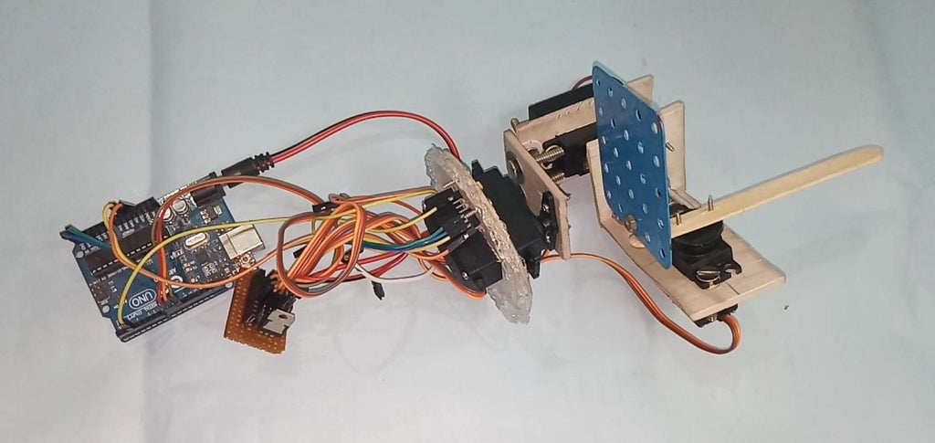
Step 9: When All the Components Are Connected ,its Look Similar to This Picture
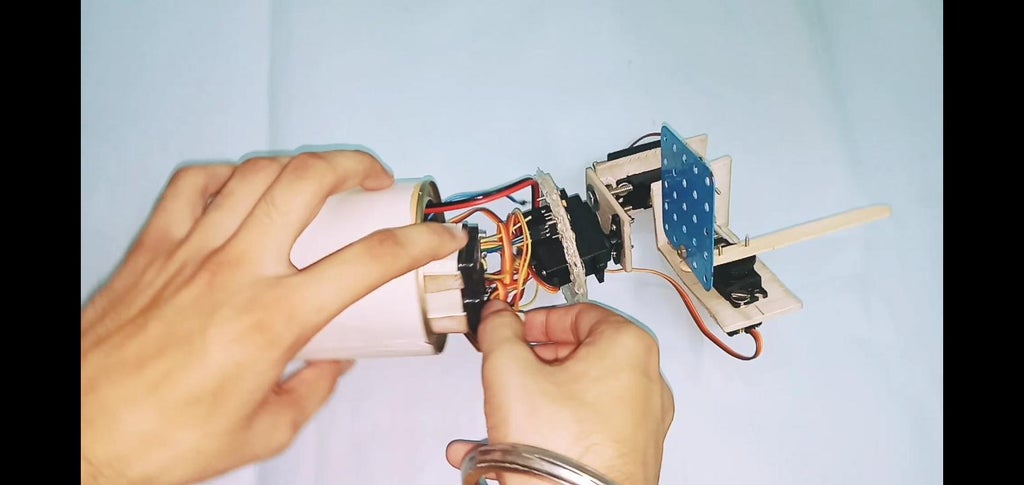
Step 10: Now Insert All Base Stuff Inside the Food Can
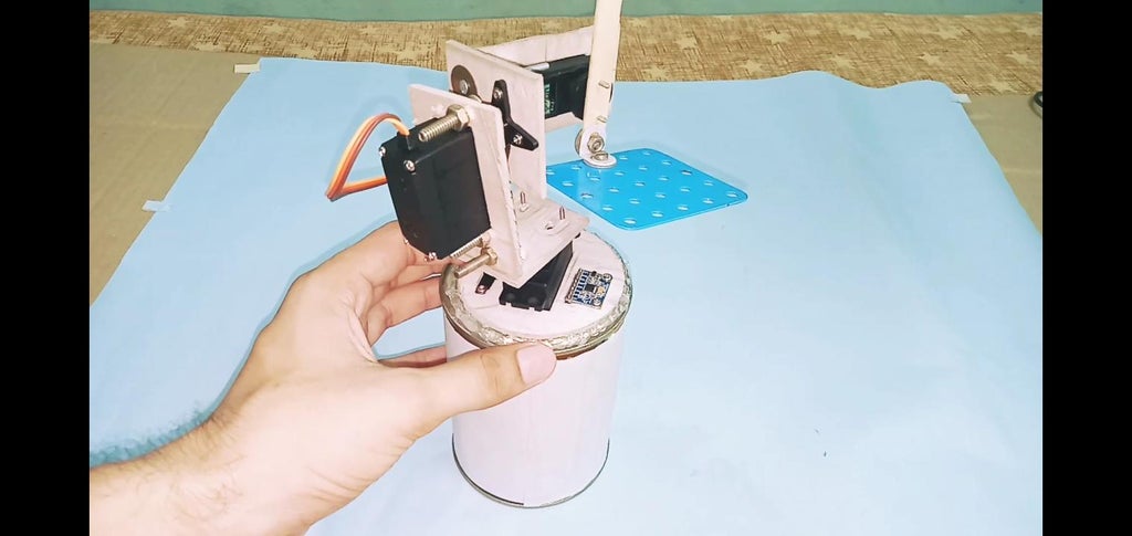
Step 11: When All the Wires and Components Are Placed Inside a Food Can Then Applied Glue Gun at the Base of Foam Board.
Step 12: Conclusion
Please note this far from good camera gimbal. The movements are not smooth because these servos are not meant for such a purpose. Real camera gimbals use a special type of BLDC motor for getting smooth movements. So, consider this project only for educational purpose.
That would be all for this tutorial, I hope you enjoyed it and learned something new. Feel free to ask any question in the comments section below and don’t forget to check my collections of project

