element14 Community
element14 Community
    Register Log In
  • Site
  • Search
  • Log In Register
  • Community Hub
    Community Hub
    • What's New on element14
    • Feedback and Support
    • Benefits of Membership
    • Personal Blogs
    • Members Area
    • Achievement Levels
  • Learn
    Learn
    • Ask an Expert
    • eBooks
    • element14 presents
    • Learning Center
    • Tech Spotlight
    • STEM Academy
    • Webinars, Training and Events
    • Learning Groups
  • Technologies
    Technologies
    • 3D Printing
    • FPGA
    • Industrial Automation
    • Internet of Things
    • Power & Energy
    • Sensors
    • Technology Groups
  • Challenges & Projects
    Challenges & Projects
    • Design Challenges
    • element14 presents Projects
    • Project14
    • Arduino Projects
    • Raspberry Pi Projects
    • Project Groups
  • Products
    Products
    • Arduino
    • Avnet Boards Community
    • Dev Tools
    • Manufacturers
    • Multicomp Pro
    • Product Groups
    • Raspberry Pi
    • RoadTests & Reviews
  • About Us
  • Store
    Store
    • Visit Your Store
    • Choose another store...
      • Europe
      •  Austria (German)
      •  Belgium (Dutch, French)
      •  Bulgaria (Bulgarian)
      •  Czech Republic (Czech)
      •  Denmark (Danish)
      •  Estonia (Estonian)
      •  Finland (Finnish)
      •  France (French)
      •  Germany (German)
      •  Hungary (Hungarian)
      •  Ireland
      •  Israel
      •  Italy (Italian)
      •  Latvia (Latvian)
      •  
      •  Lithuania (Lithuanian)
      •  Netherlands (Dutch)
      •  Norway (Norwegian)
      •  Poland (Polish)
      •  Portugal (Portuguese)
      •  Romania (Romanian)
      •  Russia (Russian)
      •  Slovakia (Slovak)
      •  Slovenia (Slovenian)
      •  Spain (Spanish)
      •  Sweden (Swedish)
      •  Switzerland(German, French)
      •  Turkey (Turkish)
      •  United Kingdom
      • Asia Pacific
      •  Australia
      •  China
      •  Hong Kong
      •  India
      •  Korea (Korean)
      •  Malaysia
      •  New Zealand
      •  Philippines
      •  Singapore
      •  Taiwan
      •  Thailand (Thai)
      • Americas
      •  Brazil (Portuguese)
      •  Canada
      •  Mexico (Spanish)
      •  United States
      Can't find the country/region you're looking for? Visit our export site or find a local distributor.
  • Translate
  • Profile
  • Settings
Simple Electronic Repairs
  • Challenges & Projects
  • Project14
  • Simple Electronic Repairs
  • More
  • Cancel
Simple Electronic Repairs
Blog Repair of tone control circuit in old transistor radio
  • Blog
  • Documents
  • Files
  • Members
  • Mentions
  • Sub-Groups
  • Tags
  • More
  • Cancel
  • New
Join Simple Electronic Repairs to participate - click to join for free!
  • Share
  • More
  • Cancel
Group Actions
  • Group RSS
  • More
  • Cancel
Engagement
  • Author Author: kk99
  • Date Created: 6 Nov 2017 4:12 PM Date Created
  • Views 4591 views
  • Likes 6 likes
  • Comments 9 comments
  • backtoanalogch
  • simpleelectronicch
  • restorerepairch
Related
Recommended

Repair of tone control circuit in old transistor radio

kk99
kk99
6 Nov 2017
image

Simple Electronic Repairs

Monthly project competitions, chances to earn prizes, you decide project themes, your ideas, your projects, turn ideas into projects.

Back to The Project14 homepage image

Project14 Home
Monthly Themes
Monthly Theme Poll


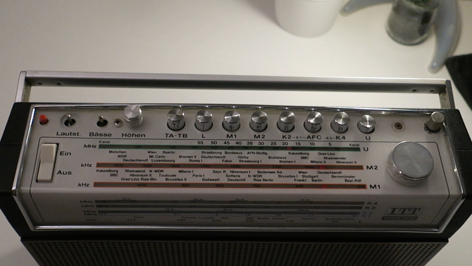
I have an old radio ITT Schaub-Lorenz Touring International 103 which had small issue with bass control circuit. Issue was caused by "cold joint" around the potentiometer used for bass regulation.


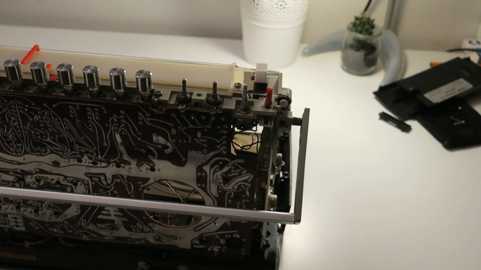
Here are steps of the radio disassembly:

1. Remove the knobs from top panel.

image

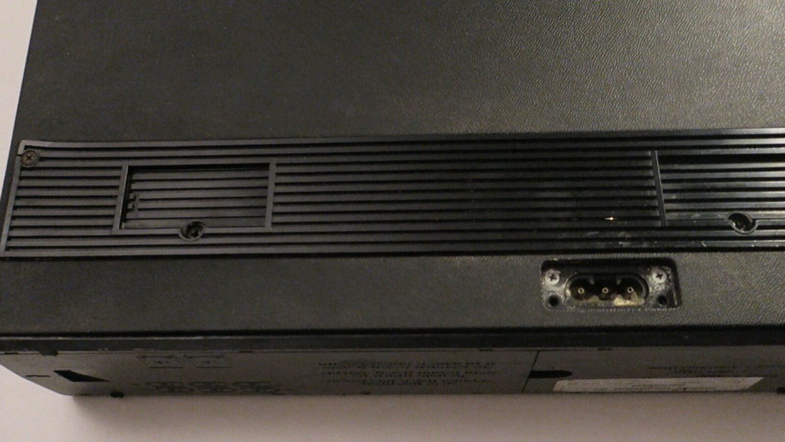
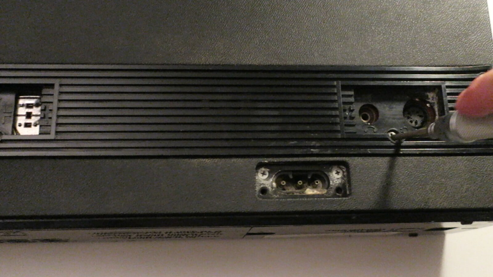
2. Unscrew all screws from rear panel.

image

image

image

image

image

image

3. Unscrew all screws from top panel.

image

image

4. Remove rear panel.

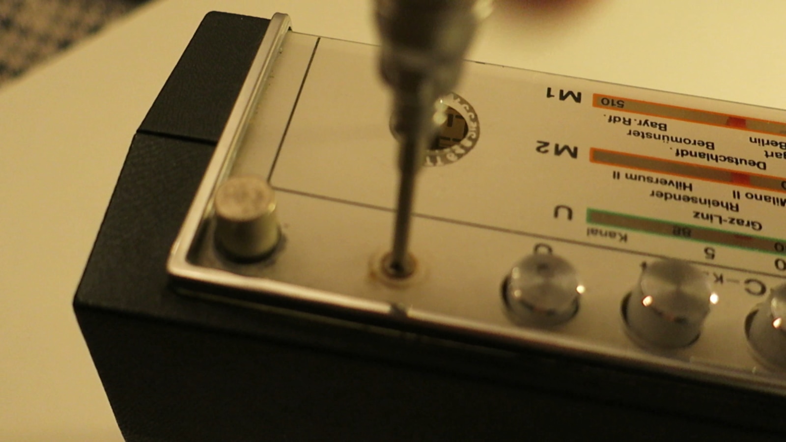
5. Unscrew two screws located near the handle.

image

6. Remove front panel. Be careful because speakers are connected with wires to main board.
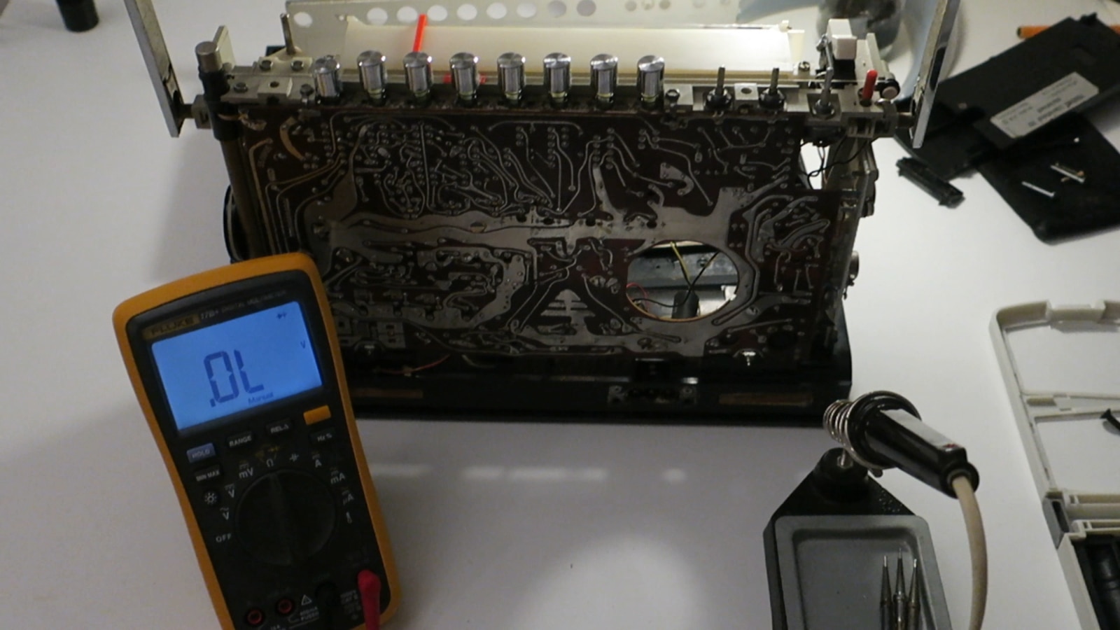
image


Debugging part.

image

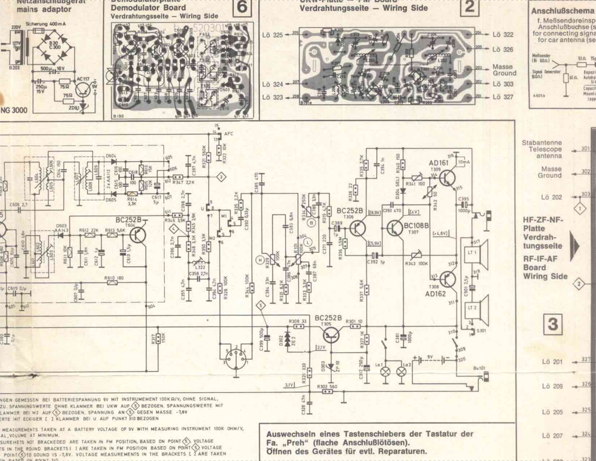
After short analysis of part of schematic related to tone control circuit and quick measurements of continuity I have found that issue was caused by "cold joint". There was no connection between of R334 potentiometer and C388 capacitor. The "cold joint" was marked by red square on one of following pictures.

image

image

image

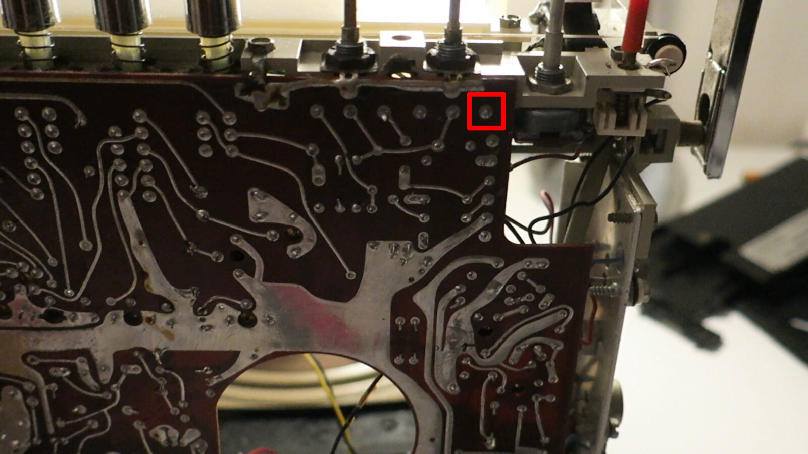
After re-soldering of this joint, the issue was fixed. Here is short video of disassembled radio.

You don't have permission to edit metadata of this video.
Edit media
x
image
Upload Preview
image


Here is short video after issue fix.

You don't have permission to edit metadata of this video.
Edit media
x
image
Upload Preview
image

  • Sign in to reply

Top Comments

  • jw0752
    jw0752 over 7 years ago +4
    I wonder how much of this great equipment ends up in the trash each year for lack of someone to just do a small repair like this? Nice job. John
  • kk99
    kk99 over 7 years ago in reply to e14phil +4
    Hi Phil, According to schematic it is printed inductor and it is part of intermediate frequency circuit. Here is this part of schematic: Here is corresponding part of PCB layout: Additionally everything…
  • DAB
    DAB over 7 years ago +3
    Nice example of a legacy equipment repair. DAB
Parents
  • shabaz
    shabaz over 7 years ago

    Awesome repair log. Thanks for showing the board detail too, it was nice to see the little touches, the designers had fun : )

    image

    I have a (far less exotic) pocket radio to repair sometime, it has some noisy slider volume controls : (

    • Cancel
    • Vote Up +3 Vote Down
    • Sign in to reply
    • More
    • Cancel
  • e14phil
    e14phil over 7 years ago in reply to shabaz

    What a beautiful PCB, is anyone aware if the 3 spirals on the left have any function other than artistic flair?

    • Cancel
    • Vote Up +3 Vote Down
    • Sign in to reply
    • More
    • Cancel
  • shabaz
    shabaz over 7 years ago in reply to e14phil

    Hi Phil,


    I'm only guessing, but probably it is partial artistic flair : ) and maybe partially acting like an inductor, it was common to put a very tiny ferrite bead on a transistor leg, if there was a risk of it oscillating. I can't tell if this is on a transistor leg, but it is possible the designers saved the ferrite and made the pattern instead. Since there are three of them, it could be a high gain RF amplifier portion maybe.

    I quite like the octopus above it : ) and the inverted earth symbol or Xmas tree : )

    • Cancel
    • Vote Up +1 Vote Down
    • Sign in to reply
    • More
    • Cancel
Comment
  • shabaz
    shabaz over 7 years ago in reply to e14phil

    Hi Phil,


    I'm only guessing, but probably it is partial artistic flair : ) and maybe partially acting like an inductor, it was common to put a very tiny ferrite bead on a transistor leg, if there was a risk of it oscillating. I can't tell if this is on a transistor leg, but it is possible the designers saved the ferrite and made the pattern instead. Since there are three of them, it could be a high gain RF amplifier portion maybe.

    I quite like the octopus above it : ) and the inverted earth symbol or Xmas tree : )

    • Cancel
    • Vote Up +1 Vote Down
    • Sign in to reply
    • More
    • Cancel
Children
No Data
element14 Community

element14 is the first online community specifically for engineers. Connect with your peers and get expert answers to your questions.

  • Members
  • Learn
  • Technologies
  • Challenges & Projects
  • Products
  • Store
  • About Us
  • Feedback & Support
  • FAQs
  • Terms of Use
  • Privacy Policy
  • Legal and Copyright Notices
  • Sitemap
  • Cookies

An Avnet Company © 2025 Premier Farnell Limited. All Rights Reserved.

Premier Farnell Ltd, registered in England and Wales (no 00876412), registered office: Farnell House, Forge Lane, Leeds LS12 2NE.

ICP 备案号 10220084.

Follow element14

  • X
  • Facebook
  • linkedin
  • YouTube