element14 Community
element14 Community
    Register Log In
  • Site
  • Search
  • Log In Register
  • About Us
  • Community Hub
    Community Hub
    • What's New on element14
    • Feedback and Support
    • Benefits of Membership
    • Personal Blogs
    • Members Area
    • Achievement Levels
  • Learn
    Learn
    • Ask an Expert
    • eBooks
    • element14 presents
    • Learning Center
    • Tech Spotlight
    • STEM Academy
    • Webinars, Training and Events
    • Learning Groups
  • Technologies
    Technologies
    • 3D Printing
    • FPGA
    • Industrial Automation
    • Internet of Things
    • Power & Energy
    • Sensors
    • Technology Groups
  • Challenges & Projects
    Challenges & Projects
    • Design Challenges
    • element14 presents Projects
    • Project14
    • Arduino Projects
    • Raspberry Pi Projects
    • Project Groups
  • Products
    Products
    • Arduino
    • Avnet Boards Community
    • Dev Tools
    • Manufacturers
    • Multicomp Pro
    • Product Groups
    • Raspberry Pi
    • RoadTests & Reviews
  • Store
    Store
    • Visit Your Store
    • Choose another store...
      • Europe
      •  Austria (German)
      •  Belgium (Dutch, French)
      •  Bulgaria (Bulgarian)
      •  Czech Republic (Czech)
      •  Denmark (Danish)
      •  Estonia (Estonian)
      •  Finland (Finnish)
      •  France (French)
      •  Germany (German)
      •  Hungary (Hungarian)
      •  Ireland
      •  Israel
      •  Italy (Italian)
      •  Latvia (Latvian)
      •  
      •  Lithuania (Lithuanian)
      •  Netherlands (Dutch)
      •  Norway (Norwegian)
      •  Poland (Polish)
      •  Portugal (Portuguese)
      •  Romania (Romanian)
      •  Russia (Russian)
      •  Slovakia (Slovak)
      •  Slovenia (Slovenian)
      •  Spain (Spanish)
      •  Sweden (Swedish)
      •  Switzerland(German, French)
      •  Turkey (Turkish)
      •  United Kingdom
      • Asia Pacific
      •  Australia
      •  China
      •  Hong Kong
      •  India
      •  Korea (Korean)
      •  Malaysia
      •  New Zealand
      •  Philippines
      •  Singapore
      •  Taiwan
      •  Thailand (Thai)
      • Americas
      •  Brazil (Portuguese)
      •  Canada
      •  Mexico (Spanish)
      •  United States
      Can't find the country/region you're looking for? Visit our export site or find a local distributor.
  • Translate
  • Profile
  • Settings
Smart Alarm Clock
  • Challenges & Projects
  • Project14
  • Smart Alarm Clock
  • More
  • Cancel
Smart Alarm Clock
Blog Tempus Fugit... Part 4: micro:bit 5V SPI
  • Blog
  • Forum
  • Documents
  • Events
  • Polls
  • Files
  • Members
  • Mentions
  • Sub-Groups
  • Tags
  • More
  • Cancel
  • New
Join Smart Alarm Clock to participate - click to join for free!
  • Share
  • More
  • Cancel
Group Actions
  • Group RSS
  • More
  • Cancel
Engagement
  • Author Author: balearicdynamics
  • Date Created: 28 Jul 2018 7:59 AM Date Created
  • Views 1495 views
  • Likes 8 likes
  • Comments 3 comments
  • micro:bit
  • transistor
  • vintage clock
  • vintage
  • advanced micro:bit projects
  • microbit projects
  • smartalarmch
  • microbit
  • smartalarmclockch
  • spi
  • advanced_microbit_projects
  • smart alarm clock
  • setp-up
  • alarm clock
  • open collector
  • smart clock
  • protocol
  • communication
Related
Recommended

Tempus Fugit... Part 4: micro:bit 5V SPI

balearicdynamics
balearicdynamics
28 Jul 2018
image

Smart Alarm Clock

Enter Your Electronics & Design Project for Your Chance to Win a $100 Shopping Cart!

Back to The Project14 homepage image

Project14 Home
Monthly Themes
Monthly Theme Poll


    • Introduction
    • Circuit Making
    • Programming Before Connecting!
    • Testing the Signals Quality
    • Issue Solved
    • The Other Parts

Introduction

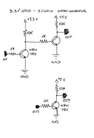
Based on the test circuit presented in the previous blog post I have created the three pins open collector and I/O inverter circuit to interface the micro:bit with the 5V SPI 7-Segments display controller.

As a matter of fact, I have only applied the two NPN transistors circuit shown below (a reminder...) to the micro:bit pins 13, 14, 15 dedicated to the SPI protocol.

image

Circuit Making

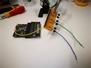
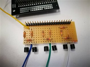
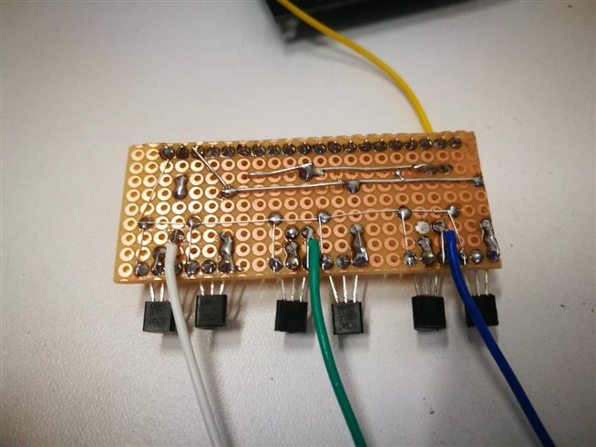
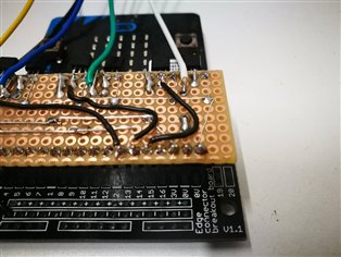
The below images shows the circuit assembled on a small piece of prototype board. The building of the clock required a series of different small circuit parts for better usage of the clock case internal space.

imageimage

image

imageimage

Programming Before Connecting!

The first time I plugged the micro:bit in the circuit without caring of what was the program flashed on the board the three transistors become extremely hot in few seconds while the board power led was not lighting. Also without seeing the magic blue smoke, I thought it was the time to say goodbye to my board. Instead, it worked fine when powered it again after unplugging.

I spent an hour testing the circuit in depth and everything was correct, no short-circuits, no wrong soldering etc. Nothing was different as expected.

The last suspect was about the logic levels. As the micro:bit SPI pins 13, 14, 15 was never used they probably drain a lot of current generating this unexpected issue. Not so difficult to verify, I wrote down the simple program shown below"

image

It is a simple loop sending alternate 010 and 101 outputs to the SPI pins with a delay of 10 ms. Ok, it's a very crap software but should work in this case. After flashing it, I plugged the micro:bit board in the circuit and heating no longer appeared.

What I learned from this lesson: It is a good practice to avoid GPIO signals out of control when connecting a circuit for testing image

Testing the Signals Quality

Leaving the program running, I tested the three output signals to the oscilloscope. The levels were very stable with an obvious delay due to the logic of the program

image

Until now I was lucky, let's see what I can do in the next steps.


Issue Solved

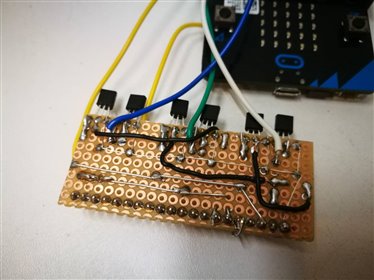
Thanks to John Clift (jc2048 now mentioned correctly...) the reason of the superheating of the transistors is due to the missing 1K resistor between the micro:bit SPI pins and the base of the transistor. After his comment I proceeded to update the circuit as shown in the images below:

imageimage

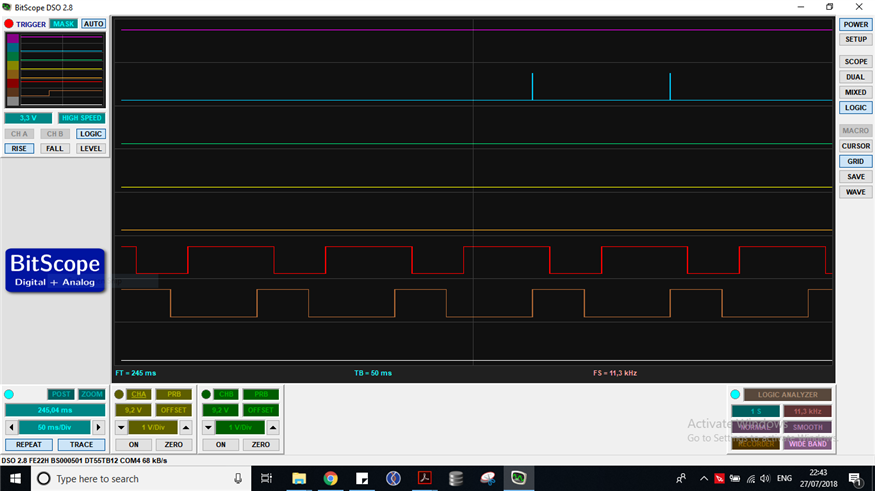
Testing the circuit it worked perfectly as shown on the oscilloscope screen below. Thanks John!

image

Note that the output tracks correspond, respectively to pins 13, 14, 15. As pin 13 is the first to be set and reset, accordingly with the program the second track is 10ms shorter and the third is 20ms shorter. For the same reason, every track is shifted along the time of 10 ms


The Other Parts

Tempus Fugit... Part 1: 1978 a.d.

Tempus Fugit... Part 2: 2018 a.d.

Tempus Fugit... Part 3: micro:bit Interfacing 5V Logic

  • Sign in to reply

Top Comments

  • balearicdynamics
    balearicdynamics over 7 years ago in reply to jc2048 +4
    jc2048 Thanks John! I checked so many times and didn't saw this detail. I'll provide immediately Enrico
  • jc2048
    jc2048 over 7 years ago +3
    Your circuit has 4 resistors for each channel. 12 in total. Your board only has 9. I think you've might have missed off the base resistor for the first transistor. That would explain the micro:bit being…
  • genebren
    genebren over 7 years ago +3
    Nice update on your alarm clock blog series. Heat, but no smoke, is much better than instant smoke. Gene
  • balearicdynamics
    balearicdynamics over 7 years ago in reply to jc2048

    jc2048 Thanks John!

    I checked so many times and didn't saw this detail. I'll provide immediately image


    Enrico

    • Cancel
    • Vote Up +4 Vote Down
    • Sign in to reply
    • More
    • Cancel
  • genebren
    genebren over 7 years ago

    Nice update on your alarm clock blog series.  Heat, but no smoke, is much better than instant smoke.

    Gene

    • Cancel
    • Vote Up +3 Vote Down
    • Sign in to reply
    • More
    • Cancel
  • jc2048
    jc2048 over 7 years ago

    Your circuit has 4 resistors for each channel. 12 in total. Your board only has 9.


    I think you've might have missed off the base resistor for the first transistor. That would explain the micro:bit being unhappy about driving it.


    It's easily done when wiring a board like this. One method I used to use, with complicated prototypes, was to tick each component and each wire off on a copy of the schematic as they went onto the board.

    • Cancel
    • Vote Up +3 Vote Down
    • Sign in to reply
    • More
    • Cancel
element14 Community

element14 is the first online community specifically for engineers. Connect with your peers and get expert answers to your questions.

  • Members
  • Learn
  • Technologies
  • Challenges & Projects
  • Products
  • Store
  • About Us
  • Feedback & Support
  • FAQs
  • Terms of Use
  • Privacy Policy
  • Legal and Copyright Notices
  • Sitemap
  • Cookies

An Avnet Company © 2025 Premier Farnell Limited. All Rights Reserved.

Premier Farnell Ltd, registered in England and Wales (no 00876412), registered office: Farnell House, Forge Lane, Leeds LS12 2NE.

ICP 备案号 10220084.

Follow element14

  • X
  • Facebook
  • linkedin
  • YouTube