


oliverschalles 24.07.2018 16:05
Project 'GiraSol' - Oliver Schalles
Calle Calvario 15
04288 Bédar / Almeria
Spain
0034 664025031
**********************************
11th. Update, from 10. 2. 2020 @ 19:21
A real help from a friend:
An Electronic Device Producer offered me samples from a highly precisely Lux 'meter - basically a one pixel camera with programmable exposure time and aperture' ... and all to talk over the I2C bus ( VEML 6030 )
Here I won in the contest for sun energy collecting things'- the possibility to choose from ' precise electronics and stumbled over the VEML 7700, a precise luxmeter - but as I found out all devices have the same I2C address ( to communicate with it) - so the need to find out a possibility to manipulate them , to be able to talk with one of them 4 - so I asked by email the Producer, if there any posibilities' exist, to switch them devices - with the same address ?? ..
for a single device of it (VEML7700) a adafruit library with an example program for Arduino, exists. so far so good .
an hour later I got a response - "yes, it is true - you, one cannot readout' individual - devices with the same address, on the same bus ...!"
became interrupted - so next time more to it...
now:
11.2.2020.
so . what to do ? browsing around and found some ideas - I2c switching devices - switching the sda lines, cutting off the vdd to the devices ... wow .
and but - they put me on a different path: the VEML 6030 - a similar device to the 7700, but has additional pins: interrupt and : Address'assign!
when that pin is tied to gound - you have a certain - fixed adress ( 0x10 ) - and when that pin is tied to Vdd - than the address changes to 0x48.. !
wow . so one could communicate with 2 devices - addressing theirs individual address - ok ,
but still the need of 4 devices - west, east, horizont and zenith - so again, switching ??
not so good .
browsing again, until I found in a Arduino Forum: https://forum.arduino.cc/index.php?topic=466617.0 THAT idea:
to explain I need to upload a fast drawn schematic :
the sensors: # 1, 2, 3, 4 are connected paralell, I2C Bus - sda & scl, and the power to each device -
and the adress input pin of each device is connected to the out of the decoder or the GPIO pin of the arduino_ - : when switched high' the address of the device ' switches over to 0x48, and the arduino can address / comunicate / read out ' the datas..
when that line is low, (0Volts ) it has a different address in that array - and just not listening to',
when the arduino wants to talk to someone who listen to 0x48, ( like a telephone number(!) ) .
.. the genial thing is:
- for every I2C device RTC clock, a Oled Display ; here, the light sensores, and its unique features - to program' it, has to have a different, unique Library (in where is written the different addresses, often ! ) 2 adresses ? - two libs !! ( it adds up more bytes to store in the final program, that sports the arduino... )
- here we just need to communicate with only one device at a time - and so it will work to support / communicate with a device that listens to 0x40 -
- and that will be - all of them 4, here, (or 10 - if you 'want') so: when selected, by an high signal from the arduino ( by a GPIO Port ) ,
THAT device will be able communicate with the Arduino.
so only one lib, only one program that has to run 4 times, after addressing the sleeping (better said listening to an other address ) device - to establish communication - to stet the parameters and to read out, than switching to other device _ high to the address pin - and the same thing over again. ....
I could use 4 digital out pins of the arduino - but for why - when I can have 2 ?
, just need to - bin'code - the two out lines and a decoding device 2:4 ( 74'138 ) : it's out's are connected to the device address pins (after a 5 to 3.3 volt shift..) as above in the schematic .. <
for why that all ?
I build up a Photo'diode / tansistor Array - to get ' infos about where at the sky is brightest point ? - to track the sun.. yes.
so at fist again a schematic form that array - a note from my analoge notebook, a photo from it :
as we can see - we have 4 PD, and a center one - the center is intended to just measure the amount of overall light_ to detect the night / day difference -
while the 2 pairs, crosswise - for to detect the rotation of the sun - from east to west over the day - and the elevation angle from morning - horizont to noon, at zenith and back to horizont, at evening..
so them 2 pairs deliver ots analoge signals to the arduino, which detcts the amount of light form each, calculate the / a difference from a pair ( rotation / elevation) and gives the diifference, and the direction to fire the motors - high difference - motor(s) fast, small difference, motor slow, and - at no difference: motor stop - the mirror is alligned...
Ideas and Praxis :
first tests, connecting, test on stability and sensivity: ( i experimented quite a while to find out the values to the correct resistors and capacities' .. )
by aproaching the light to one of the PD in the array - one can see how the indicating LED responds to it...
here, the idea - to ' a functioning PD Array. :
and the final ' aperture:
now the PD's are 'coated with black heat'shrink tube - to prevent light coming from aside ... 

And the pcb, is coated with a laquer to prevent to 'enter atmospheric influences to the board...
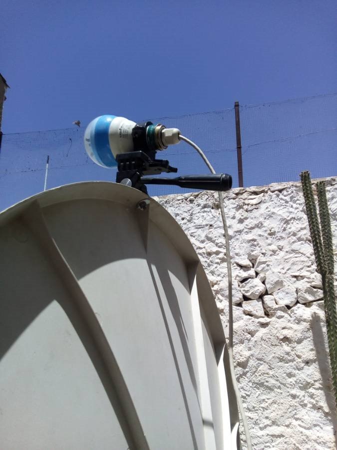
so it will be attached to the parabolic dish:
an overview' :
The 'camara' tilt and pan thing' - is is intended to 'fine-adjust the 'mechanics to the electronics...
so, that the focus is really there , where the heat collecting element is mounted on !! 

so back to the ' help from a friend -
Vishay ( I am not in any'ways ' connectet, '$$' to them ' ) -
but I asked them what to do when some devices , have same address, blah, blah,
and long story short _ they sent me - within 4 days ( Germany/ Spain )
10 samples of their VEML 6030, for free.
but these devices' so to name', are as big as 2 by 2 milimeters ,
and when one of them will fall on the floor - it will be for ever lost .
..
BUT - they are super precise, the datas one can read out, will do make sense, and one' (Arduino GiraSol Program') can 'work highly accurate with it:
to detect:
Where is the sun ???
"... or use manual soldering method ...!" ( aiiii )
2 by 2 millimeter, each... mmm . '
think, it will be a big challenge...
Ok..
Thank you for your time to read, for your interest_ 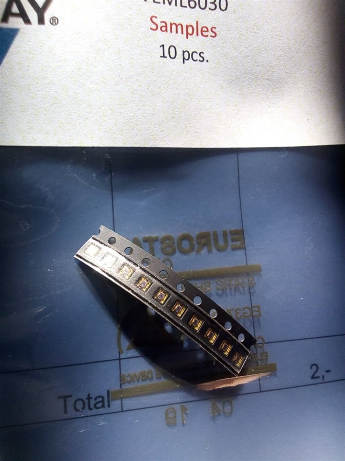
Sunny Greetings from Bedar', Andalucia.
Oliver
**********************************
10th. Update, from 5. 2. 2020 @ 15:50:
Some of the secret works behind the 'curtain:
(optical) Switches, RS Flipflop, Arduino lead to a State-Machine...
The 'State Machine' - the model I made from an old cd rom drive - and mounted on the carrier one of the switches - the other one was already attached to the frame at the other end'point... the switches triggers the R or the S input of the flipflop, so that the out of the FF either has 'high': going to 'west', or 'low': going east, depending on the direction the carrier moves..
That model (to get the code for the Arduino, and to see if any obstacles may occur', BEFORE I would let that Program 'sport' the real big motor for the GiraSol... I attached the optical endswitchs to the GiraSol X axis 'recently ', so now, the 'need for the model... made some videos from it : but I want to start with the layout from the RS FlipFlop,
(drawn in Eagle, exported the design via Lasertoner'transfer on a real, double sided' pcb, etched, drilled and 'populized it) - and - was already build into the GiraSol -Box, so I needed to simulate on a breedboad - the FF, for that State Machine 'model...
The Arduino detects the low/ high change on one digital input pin, and drives accordingly to it the 2 PMW out lines' - reversing the - one PWM, the other, to ground - so the motor spins with its PWM speed this way or the other (clockwise / anti'clockwise) ...
Directly after power'up these RS-FF's goes in a un'definite state (due to components differencies - small, but...)
So to prevent the toggel'ing to an indefinite state - there is this build-in condensator (C1, 100nF) - it takes a 'bit' longer to get completely charged, so that input (at pin 6) is a bit longer torn to ground' - long enough, to trigger the RS FF, to a definite state ...
Here two channels in the design, exactly 1:1 - one for the X axsis - rotation and one for the Y axsis - elevation..
(in the final PCB I have 1K to all inputs, the pullup's are 100K, and the IC is finally a '4093, a quad CMOS SchmidTrigger NAND..
I do really like them cmos digital ic's , for you can run them, make them work on 3 to 15 Vcc !)
and - in the JP1 - 1 & 2 are the input pins for the optical switch signals, and in JP2 you find the out's of the FF..
one of them 2 is enough to detect the direction: high or low - ( for the second is just reversed to the first )
so i decided to define: logical '1', 5 volts = goWest; and logical '0', 0 Volts - means goEast...

the CD Rom drive..
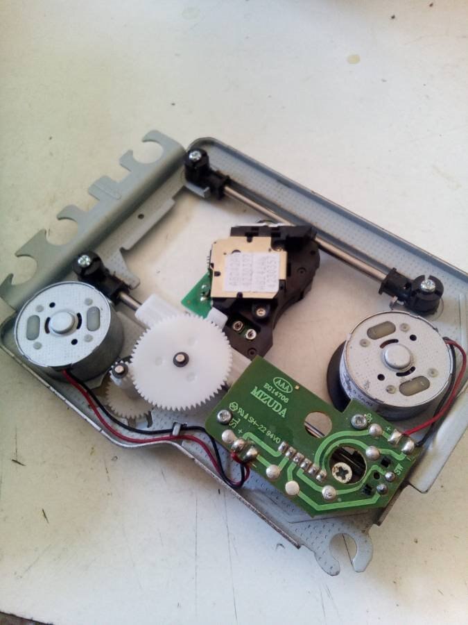
the modified drive - endswitch installed:

beedboard FF, motor-driver, while attaching to the model' ..

here you can see that 'model' running - in the background the breedboard, on witch I built the RS FF (one channel)
nice to see the outs from the FF indicated by the 2 LED's - which lits according to the direction the slider 'moves ...
the other switch is a bit hidden under the pcb, for it was already installed - I just used it - as one endswitch..
the core part of the state-machine program : (azimuth = rotation - from east to West, at daytime , and from west, at evening, back to East , to the morning start position... )
  // read the state of Azimuth input pin:, signal from output of  the RS FF //
  ffAzimuth = digitalRead(ffAzimuthPin);
  if (ffAzimuth == HIGH)                        // if FF Q Azimuth = HIGH => goWest
  {
    goWest();
    // delay(2000);
  }
  else
  {
    while (ffAzimuth == LOW)
    {
      goOst();
      // delay(2000);
    }
  }
}
// --------------------------------
void goWest()
{
  analogWrite(mot_Xb, 0);             // first: Ground
  analogWrite(mot_Xa, speed);
}
// --------------------------------
void goOst()
{
  analogWrite(mot_Xa, 0);               // first: Ground
  analogWrite(mot_Xb, speed);
}
all wired, Arduino Nano Driven:
the setup with the real machine' via the GiraSol Box; motor drivers and optical endswitches..
no smoke ? .. no... 

the rotation axis and one optical switch...
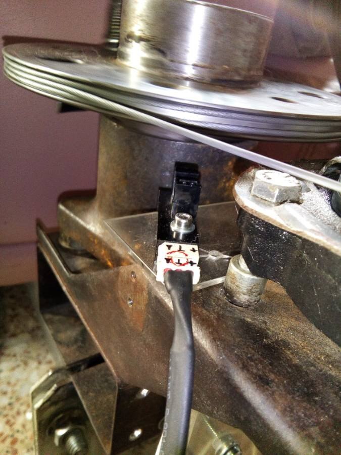
That optical Switch in ' Action:
the State Machine in full action. Program uploaded to Girasol Arduino Nano, executing..
L'adar ?
so far for today ...
thank you for your interest, for your 'patience ...
greetings to you all - from beautiful (today, not so sunny) Andalucia...
Oliver
**********************************
9th. Update, from 5. 2. 2020 @ 11:50:
News:
still alive - working on and on secretly ...
I am sorry for so long being on silence - currently buisy to care for an elderly man, ( 82 ) and that takes pretty time ...
the dish i wanted to directly metallize - is now covered' with highly reflective mirror foil, and a free'hand test - to the direct sunlight, was able to set a wooden stick on fire within 3-to 4 seconds when held directly to the focus... that, was pretty impressive for me ...
**********************************
8th. Update, from 23. 11. 2018 @ 17:30:
The optical endswitches...
the End-Switches…
as recognized - the mechanical switches I wanted to use and installed them already one year ago - they start to rust, to oxidize - so a more durable solution was in need.

I googled around in my pile of electronically parts and found - some pair of optical devices:
an infrared diode mounted in opposite to a phototransistor - so the light beam opens the collector-emitter path.. ( so a ‚ positive logic‘ )
But, to toggle the electronic in the Girasol -Electronic Box - it's expecting a signal that goes logic 'low', '0‘, so the signal had to be inverted…
The final 'switch' is to toggle the entrance (an RS Flipflop ) - the active path - an 'open-collector' draws the input to ground, to trigger ..
I need to build 2 pair optical end switches - one pair for the elevation axis, and one pair for the rotation’ ..
first schematic:
m
The detecting electronic works on breed board:
At right the 'interrupt to the 'light beam device'
The led indicate 2 channels, and one I grabbed by the oszi..
Its a bit lame, but it works perfect for my small issues - and was 25$.. (!!)
You can see, that the logic level changes from high, ( about 4.2 volts, ) to low, about, 0.7.. 0.8 volts..
Its set that one step on the screen represents 2 volts..
Normal ' MHz oscilloscope - one channel, starts at 200$; good ones, with two or even 4 inputs - at _500, digital storage, too, 1000$,
( talking about hi-end, - than open end.. goes up at 6000.. (! )
So that device ' I have is a super cheap one, digital, stores as well, all basic functones available.
And I do not megahertz, just to see if that signal chances, and how ! You can see roughly the power supply, if the power is clean '
And that's basically you need for the hobby
breadboard, one pair:
This little board is the soldered version of the breed board ...
I need 2 of them - one for rotating east/west and the other for the elevation - horizon/zenith:
When running it shows the state of the optical switches
Green - no interrupt, Red - beam is blocked, (device is at end point..)


the second device,but now with ic socket.
I removed unnecessary pins and left over the 'active pins in the socket' s
the TD62503 consists of 5 transistors - the base as open 'input, and an open collector 'output, basically -
and all emitters are connected internally to pin 8..
Only 4 of the transistors I used : the 4 inputs - and 4 open collectors (200 mA each) - and the common emitter:

connected to :
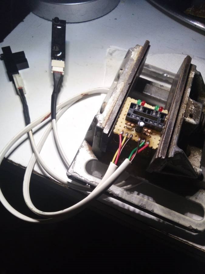
The yellow/green gives the signal; Red - positive for IR Led, black - commune negative, ground...
So have 2 pairs of detecting boards with the 4 sensors -the return points at east, west, horizon & zenith
When the machine runs 'into'an (optical) switch at its end'point, it has to stop and do reverse (by the GiraSol - Program ):
these are the detectors, to tell the program and 'it asks - is there, at that pin, connected to Arduino - a high ( 5 volts,) or low' - logic, = 0 volts ??
The following electronic, directly after, is to store the way (direction where to go ) - a toggle - RS FlipFlop tells', stores the state - if east or west switch is ' triggered, it changes its output state: on its tour to west = high', going to east = low'..
West tour ends' up - at that detector when it runs into, 'triggers‘ the switch, and the prior high signal now goes low ... = now, go east, - until you' hit the other end - the east switch..
The signal cooking, signal shaping' and toggling, does the hardware before the arduino..
The whole action is focused on - if one of them 4 reaches the switch, the toggle action is performed - the toggle line is connected to arduino, and the other toggle signal - as well to the Arduino. One of these signals ( high/ low) triggers the 'Service Interrupt Routine', ( at pin D2/3 ) witch calls a routine, wto look what state that toggle signal has:
all members in the program is now informed, that the 'goto-west' direction has changed - now it shall 'go east'.
for having 2 motores, all has to be double, so 2 interrupt pins, and 2 toggle signal pins..
So the need of 4 detectors…
***
so far, theoretically …
Next day I found out, that the strange behaviour (sometimes a randomly’ triggering) of one pair I recognized - at test phase with them big' ones, -
was due a mistake I made:
I assumed that the devices were build up similar, consisting just one IR LED and a Phototransistor - but after a check and download the data sheets -
I saw that the bigger ones were completely ready - no need for a resistor for the IR LED:
just to connect to Vcc, Ground - and having than, the open collector to use ( iCE @ 40 mA ) ….
The 'small' one from sharp is the simple version, diode / photo transistor..
- the big one has it's electronic' already built-in: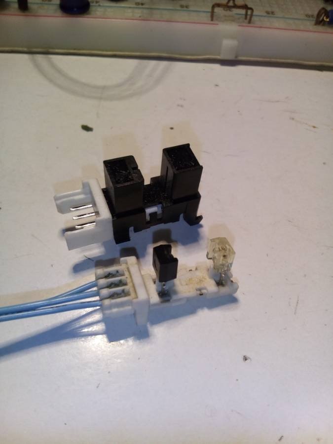
So I needed to skip, simply, just short out' the 350 ohm resistor, to sufficiently power up the device.
The resistor - limited the power, the device needed to run fully: so that strange behaviour is/was 'caused by not sufficient supply voltage..: 

the cables have to be well 'isolated - not prior against electricity - but against moisture..
to identify: the + pole is the shorter one ..

now, than: measuring cable' length, attached some jacks, designed the PCB where the two pairs of signals have to go in,
to be shaped and amplified, to go to the GiraSol-Box'
A spiralchord from an telephone gives free movement for the senselevation detectors, of course, they are moving with the mirror, so there the rotation'..
Now, the last 3 days ‚in’ to build a lil board that does, in fact, trigger the switch inputs of the GiraSol-Box,
Had to open the box to see if my cable to them devices having the same color-lines connected throu'..
And that thing, the attempt’ was OK, but did not work to trigger:
So I've had to change the design, and found a even better solution :
now the final’ switch/trigger/contact to the RS FlipFlop - will be done with optocouplers ( its IR Diode in series with the visible LED) The open collector, draws the input 'low, perfect to trigger !!!
It does it’s work,now, yesterday evening until this morning - reliable, all states were fast and well recocnized and super stable':
Right, bottom, the cable jacked in'to the GiraSol.box...

the 6 wire cable to the output pins have to have a socket’ to the cable to push-in to the jack of the GiraSol Box…:

Red is Vcc ( +5V)
white is ground,
Black - west
Yellow - east
Green - horizont
Blue - zenith
(Lakota colours to the directions)
It works like a charm...
Set & reset, by 2 devices, 4 sensors, - connected to the GiraSol.Box:
A one year task: now ready, done ..
These sensors I found in a big copy machine and had them all in my ‚scrap box‘
2 months ago, the optocoupler I used here (4 in one) came from Farnell, from the price I won on here, on Element14 !! ( Huuuurraaaayyyy !!!!)
So all came together at the right time..
These optical switch devices - now - has to be mount to the real machine..
Next steps lead to new updates…
warm greetings, despite from pretty fresh and wet weather, now, in Andalucia..
Oliver
**********************************
7th. Update, from 23. 11. 2018 @ 14:30:
reorganizing the 'blog, for better radar'bility:
now the updates are ordened chononogically:
actual...
...
...
...
oldest ...
Oliver
**********************************
6th. Update, from 19. 10. 2018 @ 23:06:
a biig 'Thank You' to the Element14 community :
The resistors and the ic's.. : 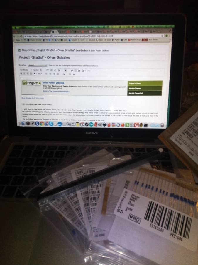
It's just a small part of it, the other electronics I received 4 days later, after choosing from all their components from Farnel
I did not expect them any more - for, due to the high shipping prices, I e'mailed to Tariq - who finally did the order for me, that he should skip the resistors -
but as I saw today, he must have 'ignored' it, and so, the resistors were sent to me..
so again - Thank you so much 
Oliver
**********************************
5th Update, from 17. 10. 2018 @ 20:08:
the cleaning, polishing action, with abrazive whitening toothpaste - and the diy - polisher..
the material to polish :
the tool to it :
And, the result from today.. ( better as I thought ) - the 'reflectivity' - after1-hour polishing -
I even could hear the different areas where it was dull while polishing'..
After working on, the sound legalized to other already done areas:
the better, finer, smoother, the better the reflective layer, every fanit scratch, or dullness, one can see, alike magnified on the result.
They say that silver layer one can add-on, thicker, to legalize scratches, but have no experience, practical, until now.. ( as it would behave as a 'filler.. I've to see )
After the polishing action, I sprayed, cleaned at first with tab-water, then with distilled..
of course - with my sprayer ...
The weather was nice, no wind, not too hot or cold and a clear sky, perfect working conditions.
Hope the weather will be good tomorrow, so I can do the final polish...
greetings to you all - from Andalucia -
Oliver
**********************************
4th Update, from 16. 10. 2018 @ 22:06:
the working double-spray-on-air-pistol' ...
as I promised I took a 'clip (this afternoon) from the working' pistol' - here water - and a dry wooden board to show. :
The best - ok, it works like a charm, too - it takes from the two bottles the same amount of liquid (!!!) as intended:

Next step's:
The last two polishing action - a toothpaste which whitens the teeth, abrasive, soft, and the last polish with normal toothpaste - even finer the abrasive,
- for not able to get here cerium dioxide, or titan dioxide as a fine powder, thought about to use talcum powder, but it has different, coarse grains in it.
So thinking about car polish liquid, but that is waxed or has silicone in it, and - looks nice, but as a bonding to the silver layer? Catastrophe.
Need to remove any faint of silicone than, and that would be more work, and disappointing, for it is not a real polish, but a masking, filling to the fine grooves in the lacquer, the dull, abrazed surface...
So I ended up with toothpaste, for its water-soluble and so for removable from the dish, no fillers, just real fine polishing action...
After the dish is finally polished, I need to clean with all I've in hand, fluoride, from the toothpaste, shall be removed with sulfuric acid - on the surface, after the acid, I'll remove, neutralise
with a strong base, then a water de'tensifier, and distilled water to clean all up...
I can see how the molecules work to each other !!
the last two days - a lot of rain, here...
greetings from Andalucia
Oliver
***************************************************************
3rd Update, from 12. 10. 2018:
how to 'mirrorize', to make the dish 'highly' reflective -
the need for a double-spray-on-air-pisol' - and the DIY build:
................................................................................
At first:
I have to, want wholeheartedly' say a biiig "THANK YOU" to all here, in the community, for the price I won - and for the help I received ...
I could choose the electronics - and all came to my hands - and it felt like having Christmas!
It was really thrilling for me
..................................................................................
I will go on with the updates - likewise logical - the last entry, down'under' was: - how to silverize that dish- and found out, that I do need a finer mist to spray on. -
this garden-pump-sprayer - they made too big drops, and the handling was pretty challenging.. (the liquids from each bottle has to be sprayed on, simultaneously ! )
so I looked for an other, better solution since than.
My neighbour Christobal lend me his air compressor - with a dust blower pistol, from which I unscrewed the tip - and looked around in my boxes of material' and ended up with some connectors and rings - from the garden hose. The connector, to attach the end of the hose - fitted ' accidentally ' perfect in the pistol: I even could screw it on'- with a ´bit of force, so - it was perfectly tight.

now - I could use the pistol it to fit anything on it! (a ' female' connector)
after that 'important step' - I looked further on - the male connectors to it - found two - which I could screw-on each other.
One of it I extended the outlet - with a PVC tubing, some 8 centimetres - to have the outlet for the air.
My idea - then: letting end fine tubings at the outlet, so the air will take the liquid out and form the spray...
to add in 2 little tubings from a venofix butterfly (the med-doctors use them to get a blood sample from off your vein') .
I just wanted to let them end, in the endpiece...
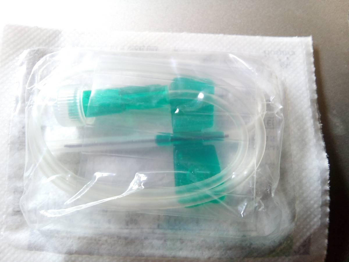
but how to get them in that housing?
I drilled 2 little holes on each side of the endpiece - oppositional' than I cut off the needles and pushed the little tubings into the housing - one left, one to the 'right -
and long enough to end up in the nozzel. A drop' of CA glue, tightend the drillings... :
the end-piece: all parts in place:

But, that 'construct' worked - for just around 5 minutes:
The air stream forced the ends of the fine tubings to vibrate - and so the ends destroyed themselves by hitting to each other ...
MMMMM... 
The need to reconstruct the entire 'end-tip':
A concrete airflow, a housing for the end of the fine tubings. Form metal. Glued, fixed together - like a pack of three.. :
wow - and again, hovering the house, was looking in all boxes, cartons. And I found' a radio antenna. The last end part was fine, but was it thin enough to fit?

tube, red shrinktube, metal tube, the end of the flexible, a toothpic in the lumen' :

Cutting, measuring, recutting, until all the 3 ends were in place - the tubing outlets for the liqids and the air tube. Before glueing the fine flexible tubes, the ends - into the fine metallic tubes, I pushed in the ends, in the lumen a tip of a waxed toothpick - to prevent that any glue would clog up the fine outlet.

airtubing and the 2 liquid dispenser tubings - that tiplet - to get in place:

here in the housing, starts the airtube:
After the ends were fine and cured I added the longer air tube - fixed altogether by shrinktube, some epoxy to the triplet and all at, in' the end of the PVC nozzle...
shrink tube forms the triplet :

a bigger shrink tube all around, to tighten all up and to stabilize. - the shorter tip is the air nozzle (red) :

all in place, ready to connect:

That construct works like a charm. It draws about 1 ml every second to nebulize...
Now, how to attach the little tubings to the liquid bottles, and a holder for the bottles - to that pistol ?
browsing the house, an empty 5-litre demin water canister would do it ':
cutting away the half of it from top to down, cutting away the unused parts -
at top of that construct a big hole to fit on to that pistol, to the garden hose connector... :
into the open syringes I can add some filter material, and they guarantee that the tubings will be well 'supplied, always submerged in the liquid..
the bottleholder, 2 x 0.5 liters:

the center drilled caps with the superflexible liquid-tubings:

after all testing all has to be cleaned, all, the working marks... yes...
next step - waiting on good weather, to clean the whole dish thoroughly, to give last polish on it, and than, the setup of new silverize-fluids -
the activator - ( tin chloride );
the silversolution itself (silver ions bound in 'aminoacid-complex')
and the recductor - (glucose and a vitamin C, organic acid )
further above, in the previous update, I posted the more complex receipt to it.
the tin chloride, the activator, - I will spray on with the pump-sprayer.
and for the reductor and the silver solution, I will use that new -
Double-Spray-On-AirGun
so long - i ll keep you updated !!
with nice regards and greetings from Andalucia -
Oliver
**********************************
2nd Update: from 23.09.2018
the history about to choose the dish, and - how to 'mirrorize', making it 'highly' reflective:
All them 'parabols' I had im my hands were coated, of course - the one I used here, shown in the video, has a core from aluminium with is massive 'coated' glass fibres X epoxy (structures on the backside) and a fine layer of it on the front..
I wet-sanded the front, with 150, 300, 500, 800, 1000 up to 1.500 - the parabol' was laid up ward, and I filled the parabolic gap with water and some drops of a dishwasher, detergent'
My grinding tool was a 30 cm round tap from a small rubbish bin...and I just followed softly (!!) the form, curve - not to change the geometry...
than the question: which way to use - to make that parabolic area highly reflective?
:
Aluminiumfoil ? , space blankets ( mylarfilm, golden and silver reflective )? adhesive reflective foil? silverize by chemics? wow.
a loot of ways, one as bad and unpractical, as cutting the foil in stripes, glueing them, step by step, to cover the entire area, (glueing? - with what? - a glue that contains thinner in order to evaporate to cure' - how will that solvent go through mylar, a tight foil ? - no way. , so 2 components epoxy?
Idea good' (no thinner need to evaporate) - but:
Wow, what a procedure - to get the glue on, in a fine coat? You see every irregularity in/of the geometry of reflexion: even the faint layer of epoxy ruined the surface...
And, additionally - after a year, the entire work starts to get dull on the cut edges, and the mylar film 'brittled' loose, and leaving the metallization randomly on the surface: very, very bad. - Frustrating-No-Way. ...
Than, finally, I found a 'patent' to silverize 'ANY surface' as they claim - it made sense to me - and I started to achieve all the stuff I needed for...
Made the liquids, and tried'out - on a glass plate, to see if the chemismus worked - and it did.
The liquids need to be adjusted in concentration, and I found that the pump spray devices (garden center) do spray, work - but the produced drops are too big, so I need finally an air-compressor - for a finer mist ...
The silverizing solution and the reductor liquid has to be sprayed on, simultaneously and while meeting on the surface, it forms pretty immediately a fine reflective silver layer - from 10 µm to ...150 , 200 µm, depending on low long you treat the area.
On the glass plate, I found areas, where the silver layer was tightly bound to the surface - and areas, where I could just wipe the layer off, with my fingertip, but it was not intended to silverize, its intention of the probe was to see if the liquid' work as intended...)
It is highly depending on how clean you (can) work. Every fingertip, every particle, or a faint residue' of oil, grease, fat, will hinder from bonding..
The liquids have to be made with demineralized'- or even distilled water, all rinse-procedures have to be done as well of course- with dest/demin water ...
the 'receipt: liquids to silverize...
Activator, reductor & silver in solution (light sensitive ! - so I wrapped the bottles in alufoil...) 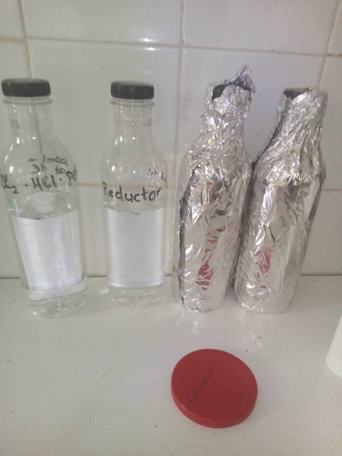
the 3 pumpspraybottles - at the location of the test - outside in the patio:
(and it silverize nearly all, but, a bit nitric acid, diluted - will swap it all clean again ... )

overall silver ! - here to remark: at the areas where the activator could reach - there, the layer is very,
very tightly bound - even to ceramic... !

the outcome from the first test, a spray on, some 4 seconds. So the layer is ultra thin and the object has to be highly clean before...
the 3 liquids:
1.: the activator contains stannum, tin ions (tin chloride) that gives any surface the possibility that the silver will have 'starting points -
from where the micro crystals do grow from - to form the metallic, conductive silver layer.
2.: the 'reductor' is based on organic acids, glucose (kind of sugar), and vitamin C
3.: the silver solution - the main ingredient: Silver as 'nitrate (water soluble) and an organic complexer' (Glycine, Amino'aethanol) that 'carries' the silver-ions..
When the reductor and the silver solution meets at the surface - the silver (iones) will be reduced to metallic silver - the reflective layer...
so far the metallizing actions - when I do spray it on the parabolic - I let you know from, of course ..
when once - the reflective layer is applied -
I have to clear it out, even to polish at certain areas - and then there is the need for a final UV protective, clear, fine lacquer coat,
witch the silver protects from atmospheric influences...
Oliver
my facebook
account - if someone wants to contact me there, too, you are welcome!
https://www.facebook.com/oliver.schalles.9
**********************************************
1st Update: from 19.09.2018
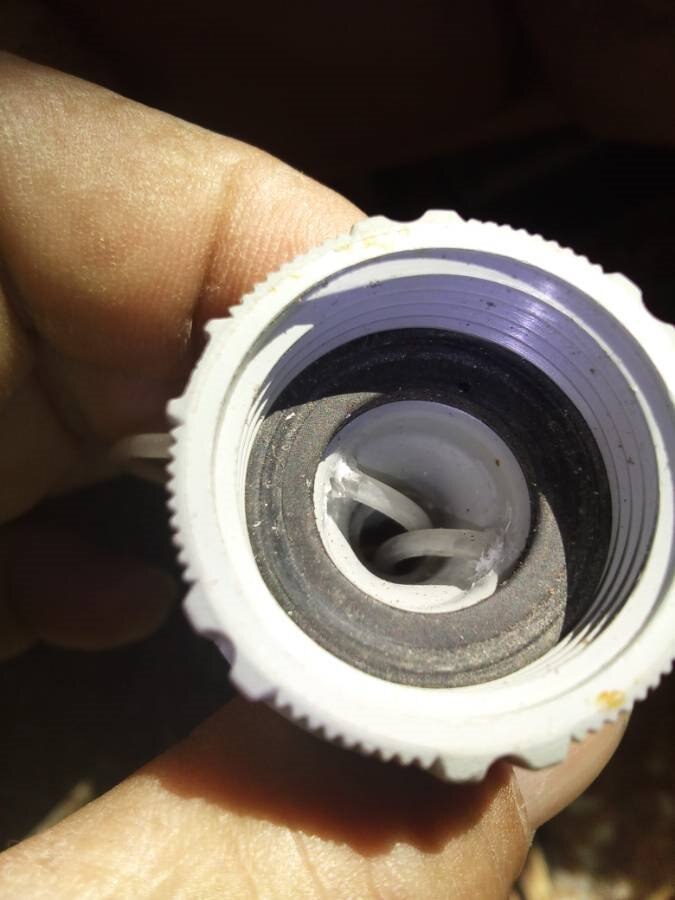
the 'new construction to the elevation axis -
the force was so strong
that the old rod nut was
pushed out of its harness...
wow. - I was looking for a new possibility to order the entries - found until now ' nothing - so I will append the material I do have.
Today I completely was able to renew the elevation 'system:
the motor, the connection from the motor housing, case to the bear 'ring'housing was wobbling, so I used just a piece
of a wider metallic tube and resined (epoxy) the gap in between the housing of the motor and the bear'ring housing... perfect tight and rigid, now. ( some days ago ) ..
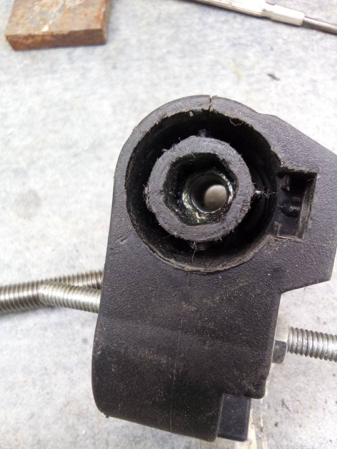
The rod nut, in its housing ' rod-nut-holder' -
a long 'nut, hexagonal, glued in - as well with epoxy. To make it 'fit in - I widened the existing channel, and
dremel'ed in, the hex profile, so
the long nut finally fitted in..
As well some days ago
.
and the
todays
' work: the strengthening to the sides, which carry, will hold the rod nut'-holder... (the nearly triangular pieces of metal, with the
bore hole
for the axis) - glued to the
innerside
of the down-under-part of that parabol.. :
Here to see the motor, the rod and the housing of the hex-long-screw-nut', and the triangular strengtheners':
the hex-nut, glued in the holder (epoxy) 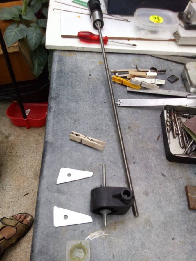
the triangular strengthener'
does all fit to each other?
close'up of the hex-housing'
aside: the nut's, M6, Inox
the motor, the black tube to the housing, and the silvery tube-housing of the bear'ring:
a shot from below, upwards: motor, rod, hex'housing, attached to the bottom of the paraboldish;
above the motor: the elevation axis..
.. about 55 degrees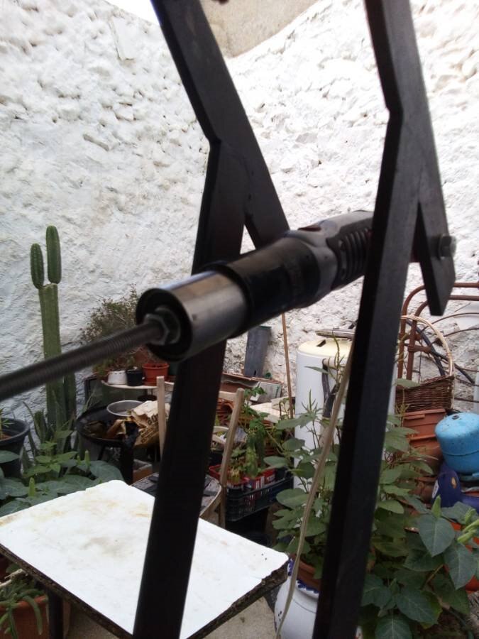


last year, what's today's left over - from the polishing action ( without the reflective silver layer !)
the laser beam reflects at first spot, to the second, to get reflected to the third. :
(5mW 405nm):

horizont' position - at evenings and in the mornings.. (we will see )

the coloum cacteea in background are Trichocerus - terchekki, -peruvianus & -panachoi..
I was totally overwhelmed - that more than 13.8 K visitors had sawn my project.
and - I do 'Thank You' for your time - to see, and look and follow, or even comment..
A good day, a good night - wherever you are - hope you are ok, and well -
greetings from Andalucia, con mucho sol -
- Oliver
******************************************************************
My first entry from 24.07.2018 16:05
I am completely new here (joined today) ...
... and have no idea about the 'what's about', but I do work on a 'heart' project - my 'GiraSol' Project, which I wanted to share with you :
its a 'device, consisting of a reflective parabolic dish, that collects sunrays, energy to a focus where a converter' (copper pipes in where a fluid gets heated up and is lead to an isolated boiler, where the heart is given into it, to the usable water - for a hot shower or to use to wash up the dishes in the kitchen - it even could be used to heat up a floor in the house...
the sunfollwer electronics, Program to calculate is made for an Arduino Nano, it has 8 analogue 'In'put pins :
5 for them photodiodes, 3 for the temperature from the boiler
2 big motor driver ic's IBT ( h.bridges for DC' motor's ), to drive by PWM the rotation motor ( east-west ) and the elevation motor ( zenith-horizont )
the sensors are made of 2 pairs of photodiodes, and a centre PD, all in all, 5.
4 End-switches, to detect the max'mechanical limits - after 2 Schmit-Trigger RS FlipFlop - polled' to 2 interrupt pins.. ( on D2, D3 @ Nano )
The thermor has got its own ArduinoUno -
for the 3 NTC - and the mechanical overtemperature switch
the temperature - coming from the Parabolic Dish, to load the thermor,
the water'temperature 'absolute, in the thermor, and -
the temperature at the out'let - back to the focus, to get reheated there again...
OpAmp followers and one comparator, to detect overtemperature,
a 0.9' Oled Display to show the current temperatures -
a pushbutton to show up the data on b.press..
I have a load of photos already posted on Facebook on its 'project page - here: the link to it:
https://www.facebook.com/Project-GiraSol-1605063979506661/
shall i do upload them photos / clips here too?? and if yes - where to ? - I definitively need help not to get lost here ...
Greetings from sunny Bédar, Andalucia, South Spain..
Oliver
first steps - 2 photodiodes, arduino nano, the sketch - listed below -
the motor driver, the dc windowlever motor, connected to the rotation axis:
(a rear-axis from a opel astra, without all them mounted stuff on it.. ) :
Overview: in front the Parabol, in the back, the thermor in which the energy will be stored in'..
a test to pan, tilt the system, to see how it responds to different voltages:
dc motors do reverse the direction of rotation when we do reverse the connections of the dc voltage.
the speed is pretty high with current, steady 12 V DC - but in work modus', the speed is really, really slow - realized via the PWM... '
PWM: tiny spikes of 12 volts -> very slow motion; 5 ... 10%
longer, wider spikes: half impulse <> half delay' - forces to spin faster: 50 %
and real big ones, long impulses witch nearly flowing to each other: the motor spins really fast ... 90%:
These impulse and pause times were repeated in nearly 1:1.000, 1:500 seconds interval.. (Arduino et al. ) depends on which pin is assigned.
the GiraSol-box - the Arduino Nano as the core - and two mighty dc motordriver for the asxis's:

 | |
 | |
Top Comments