


 | Enter Your Electronics & Design Project for Your Chance to Win a Grand Prize for the most inspiring project or a $100 Shopping Cart! | Project14 Home |
| Monthly Themes | ||
| Monthly Theme Poll |

The initial Block Diagram for the SPEC:
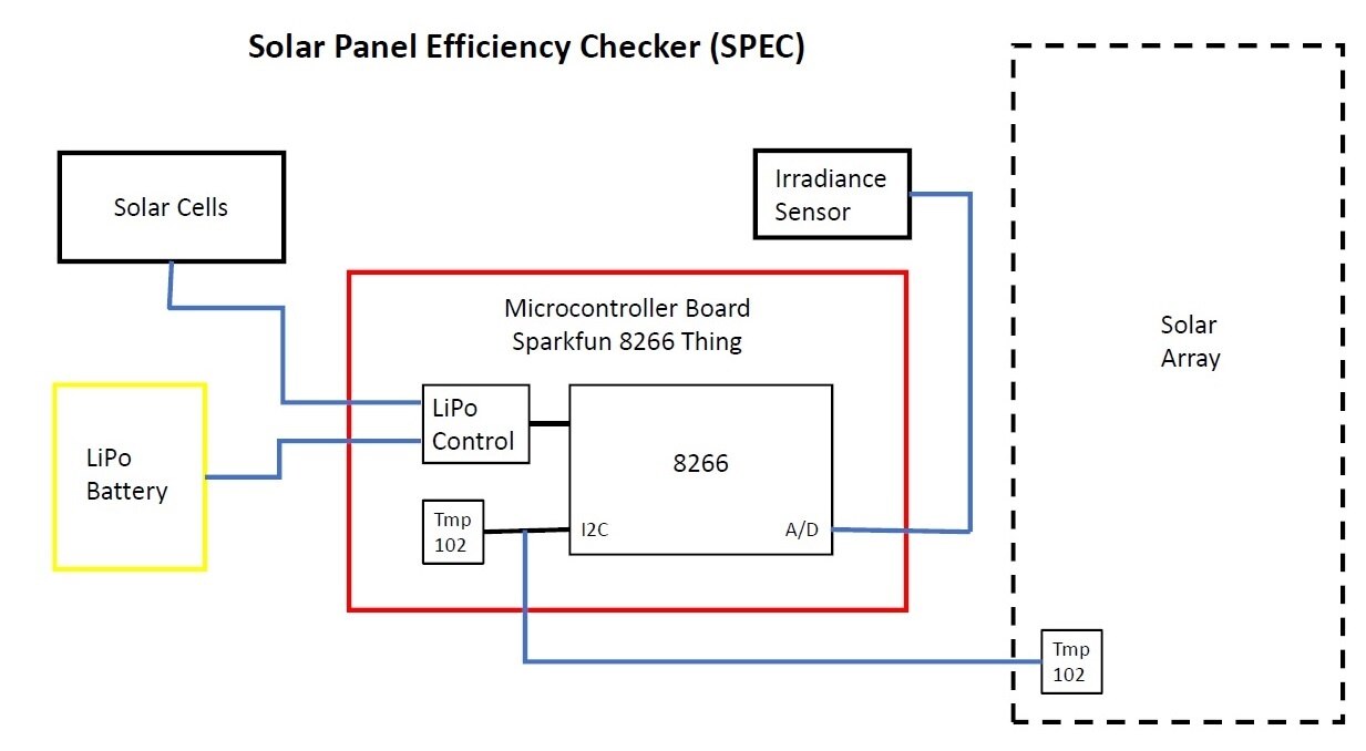
First pass at component selection:
1) Solar cells - AOSHIKE Monocrystalline Silicon Solar Cells in Epoxy Package
2V @ 160mA
50mm x 50mm x 2mm
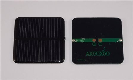
These are compact, inexpensive cells which are reasonably robust mechanically.
Use cells for both power and irradiance sensor.
2) Microcontroller Board - Sparkfun ESP8266 Thing
80mm x 30mm x 5mm
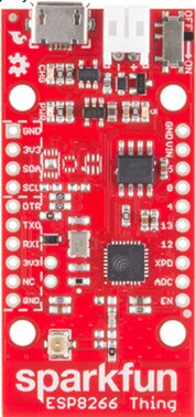
Features:
ESP8266 microcontroller
A/D Converter
I2C Interface
LiPo Battery charger
802.11n Wifi
3) Temperature Sensor (x2)
TMP102 Digital temperature sensor with I2C interface


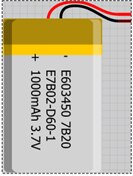
4) LiPo Battery
3.7V @ 1000mAh
5) Mechanical housing and mounts
Need a watertight and temperature tolerant box to house all the components except for the remote temperature sensor.
Must have cutouts for the solar cells.
Probably try to 3D print a custom unit.
Needs to allow mounting with the solar cells in the same plane as the solar panels being monitored.
Remote temperature sensor needs to mount to bottom of one of the solar panels (possibly just use adhesive).
Design considerations:
Power:
The ESP8266 has an average current consumption of 80mA @ 3.3V. 802.11n transmit current is typically 135mA and receive current is typically 62mA. Standby is 0.9mA.
The solar cells are rated at 2V @ 160mA, but I do not have a detailed spec sheet. I'm assuming that this is under standard test conditions. I plan to use 3 cells in series to provide 6V @ 160mA. I'll use a series diode to drop the voltage closer to 5V for the input to the Thing board. I'll need to do some characterization to ensure that I won't exceed the 6V maximum of the board input. I plan to use a 1000 or 1200mAh battery to provide power when there is no sunlight, so I think I'll be okay except for possibly a string of days with poor total irradiance (winter months). Again, I'll need to do some characterization. I can add another string of cells in parallel at the expense of a larger housing.
I'll need to have power management incorporated in the program (control the frequency and duration of WiFi activity, standby when there is no irradiance). I don't think I'll need the deep sleep mode but that could be an option at night.
Irradiance sensor:
Since I don't have a detailed spec for the solar cell, I'll need to generate the I-V curves. I'll determine the MPP voltage and current under standard test conditions (STC - 1000W/meter^2 and 25C) and use that to select the load resistor for the solar cell. I'll need to scale the load resistor voltage as the A/D input range is only 0-1V. The A/D reading will provide the voltage and current (voltage/load resistance) that are needed for the irradiance computation.
I plan to use a Daystar Irradiance meter as a reference check.
Possible additions:
1) OLED display to display irradiance and temperature locally without requiring WiFi connectivity.
2) External power switch - the Thing board has a power switch, I would just have to wire this to an external switch.
Top Comments