element14 Community
element14 Community
    Register Log In
  • Site
  • Search
  • Log In Register
  • Community Hub
    Community Hub
    • What's New on element14
    • Feedback and Support
    • Benefits of Membership
    • Personal Blogs
    • Members Area
    • Achievement Levels
  • Learn
    Learn
    • Ask an Expert
    • eBooks
    • element14 presents
    • Learning Center
    • Tech Spotlight
    • STEM Academy
    • Webinars, Training and Events
    • Learning Groups
  • Technologies
    Technologies
    • 3D Printing
    • FPGA
    • Industrial Automation
    • Internet of Things
    • Power & Energy
    • Sensors
    • Technology Groups
  • Challenges & Projects
    Challenges & Projects
    • Design Challenges
    • element14 presents Projects
    • Project14
    • Arduino Projects
    • Raspberry Pi Projects
    • Project Groups
  • Products
    Products
    • Arduino
    • Avnet Boards Community
    • Dev Tools
    • Manufacturers
    • Multicomp Pro
    • Product Groups
    • Raspberry Pi
    • RoadTests & Reviews
  • Store
    Store
    • Visit Your Store
    • Choose another store...
      • Europe
      •  Austria (German)
      •  Belgium (Dutch, French)
      •  Bulgaria (Bulgarian)
      •  Czech Republic (Czech)
      •  Denmark (Danish)
      •  Estonia (Estonian)
      •  Finland (Finnish)
      •  France (French)
      •  Germany (German)
      •  Hungary (Hungarian)
      •  Ireland
      •  Israel
      •  Italy (Italian)
      •  Latvia (Latvian)
      •  
      •  Lithuania (Lithuanian)
      •  Netherlands (Dutch)
      •  Norway (Norwegian)
      •  Poland (Polish)
      •  Portugal (Portuguese)
      •  Romania (Romanian)
      •  Russia (Russian)
      •  Slovakia (Slovak)
      •  Slovenia (Slovenian)
      •  Spain (Spanish)
      •  Sweden (Swedish)
      •  Switzerland(German, French)
      •  Turkey (Turkish)
      •  United Kingdom
      • Asia Pacific
      •  Australia
      •  China
      •  Hong Kong
      •  India
      •  Korea (Korean)
      •  Malaysia
      •  New Zealand
      •  Philippines
      •  Singapore
      •  Taiwan
      •  Thailand (Thai)
      • Americas
      •  Brazil (Portuguese)
      •  Canada
      •  Mexico (Spanish)
      •  United States
      Can't find the country/region you're looking for? Visit our export site or find a local distributor.
  • Translate
  • Profile
  • Settings
Tales for Makers
  • Challenges & Projects
  • Project14
  • Tales for Makers
  • More
  • Cancel
Tales for Makers
Forum The Predictive Maintenance Tale - piezo element voltages
  • Blog
  • Forum
  • Documents
  • Events
  • Polls
  • Files
  • Members
  • Mentions
  • Sub-Groups
  • Tags
  • More
  • Cancel
  • New
Join Tales for Makers to participate - click to join for free!
Actions
  • Share
  • More
  • Cancel
Forum Thread Details
  • State Not Answered
  • Replies 19 replies
  • Subscribers 7 subscribers
  • Views 4401 views
  • Users 0 members are here
  • predictive maintenance
  • rides and Ferris wheels
  • talesformakersch
Related

The Predictive Maintenance Tale - piezo element voltages

Jan Cumps
Jan Cumps over 2 years ago

For balearicdynamics' Tales for Makers Amusement Park, I'm making a predictive maintenance design for the rides and Ferris wheels. They have to be kept safe and in good condition. 

The project is a little piezo buzzer. In this little forum post , I show that these can generate high voltages that can damage microcontroller inputs.

image

The artwork in this story is an ode to Benoît Sokal. Comic Artist and Designer of the Syberia game.

A piezo transducer can act as speaker or sensor. I'm using it as a sensor. Piezo can generate high voltages - an element is used to generate the spark in piezoelectric stove igniters. Although these high voltages aren't generated when measuring usual mechanical vibrations, a protection circuit is advised. Even a medium tap on the sensor generates 10s of volts.

image
image source: product page of the kit I bought on Conrad

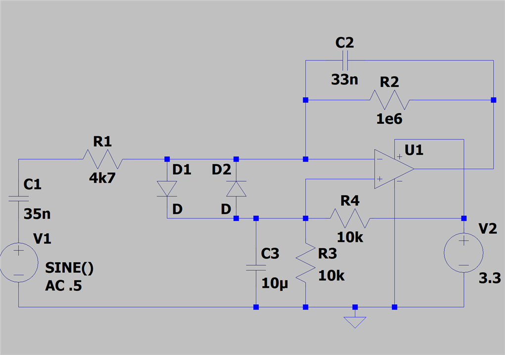
There are breakout kits from several companies for Arduino and Raspberry Pi, that come with a piezo element and a protection circuit. They all seem to deploy the same protection circuit:

image
The diode is a 5.1V Zener Diode. But let's see what happens if I hit a test probe on the board where sensor sits on:
image
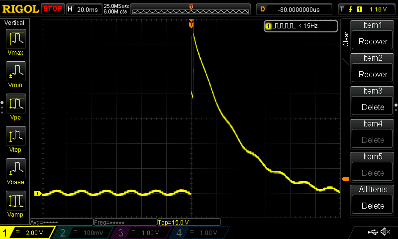
It's a "plastic on cardboard" action. I can easily generate 24 V peaks with the protection circuit in place. Not good for a 5V UNO. Most likely unhealthy for 3.3 V Arduino MKR or Raspberry Pi. If this would be mounted on metal, and a metal part would be used to hit, I'd expect the peaks to go higher. There's almost no energy - it's all voltage and for a short time. But it's voltage that often does the damage.

You don't have permission to edit metadata of this video.
Edit media
x
image
Upload Preview
image

also check out this related post:  Piezo disk as Vibration Sensor: input buffer and filter 

Additional Syberia art from this walktrough, from PlayStation store. 

  • Sign in to reply
  • Cancel

Top Replies

  • michaelkellett
    michaelkellett over 2 years ago in reply to michaelkellett +3
    Here's a way of using a single supply. You need one big decoupling cap but its very hard to see any way round that. If you give the sensor a really big thump the voltage across C3 will chang so you need…
  • michaelkellett
    michaelkellett over 2 years ago +2
    Hello Jan, Not very suprsied by the result or the badness of some of the Arduino and Pi support stuff - it's attracted a lot of very low end suppliers. There is a very old charge amp/filter fronmt…
  • Jan Cumps
    Jan Cumps over 2 years ago +2
    Action video: www.youtube.com/.../_FsigN2DZkQ
  • michaelkellett
    0 michaelkellett over 2 years ago

    Hello Jan,

    Not very suprsied by the result or the badness of some of the Arduino and Pi support stuff - it's attracted a lot of very low end suppliers.

    There is a very old charge amp/filter fronmt end ciruit on my website and I've adapted it for your sounder sensor.

    I've guessed your source capacity at 25nF.

    This circuit gives real and fast protection and band pass filtering and the ability to drive an ADC properly.

    I've modelled it with dual supplies but you can use and RRIO type CMOS amplifier with a single supply to match the ADC. (with suitable biasing of course)

    Putting the protection diodes on the summing node of the charge amp means that there is no voltage (almost) across them in normal operation so they don't screw up the LF response (which the zener across the sensor can.)

    C1 and V1 represent the sensor

    R1 sets a HF rolloff (dependent on the source capacity as well (yes the source capacity))

    C2 sets the charge gain (if C1 = C2 the output is the same as the open circuit outpuy of the sensor would have been))

    Because R1 is between the sensor and the protection diodes they will clamp the maximum input to the amplifer effectively.

    The blue trace is the voltage on the summing node.

    image

    MK

    • Cancel
    • Vote Up +2 Vote Down
    • Sign in to reply
    • Verify Answer
    • Cancel
  • Jan Cumps
    0 Jan Cumps over 2 years ago in reply to michaelkellett
    michaelkellett said:
    I've guessed your source capacity at 25nF

    It's 10 nF. I'm going to check your circuit. Thank you!

    • Cancel
    • Vote Up 0 Vote Down
    • Sign in to reply
    • Verify Answer
    • Cancel
  • Jan Cumps
    0 Jan Cumps over 2 years ago in reply to michaelkellett

    I installed a fresh LTSpice, updated my KiCad. I'll get going now.

    In the meantime, I received a second piezo element. It was on backorder since begin July. This one is 34.5 nF.

    Both the original one (10 nF) and this one are measured after calibrating the LCR meter.

    • Cancel
    • Vote Up 0 Vote Down
    • Sign in to reply
    • Verify Answer
    • Cancel
  • Jan Cumps
    0 Jan Cumps over 2 years ago in reply to Jan Cumps

    Simulation results. I saw on your website that you used an LT071, so I downloaded the model from TI, and drew an opamp symbol for it.
    changes:

    • BAV99HM are no longer advised for new designs, suppliers suggest HY variant.
    • 35 nF capacity for the piezo

    It has been some time since I used LTSpice, the muscle memory was gone, but I got it working:

    image

    • Cancel
    • Vote Up 0 Vote Down
    • Sign in to reply
    • Verify Answer
    • Cancel
  • Jan Cumps
    0 Jan Cumps over 2 years ago in reply to Jan Cumps

    In volts:
    image

    • Cancel
    • Vote Up 0 Vote Down
    • Sign in to reply
    • Verify Answer
    • Cancel
  • Jan Cumps
    0 Jan Cumps over 2 years ago in reply to Jan Cumps

    KiCad schematic

    image image

    image

    edit: the charge capacitor is to be adapted to the capacity of the piezo element (see Michael's post above, and his paper). My element has 35 nF capacity. When I use a 33 nF value in the simulator, I get a response that's close to 0dB. With a 22 nF, it bops up to +4 dB

    33 nF (match the input element)

    image

    22 nF:

    image

    • Cancel
    • Vote Up 0 Vote Down
    • Sign in to reply
    • Verify Answer
    • Cancel
  • Jan Cumps
    0 Jan Cumps over 2 years ago in reply to Jan Cumps

    image image

    michaelkellett, is it OK to have your name on schematic and pcb?

    • Cancel
    • Vote Up 0 Vote Down
    • Sign in to reply
    • Verify Answer
    • Cancel
  • scottiebabe
    0 scottiebabe over 2 years ago in reply to Jan Cumps

    Nice little TIA circuit! If you are going to make a PCB, you may want to try making a single-supply version too.

    There are lots of low-cost CMOS op-amps, ex: MCP601 nothing special about it all other than that you can still get them in DIP.

    • Cancel
    • Vote Up 0 Vote Down
    • Sign in to reply
    • Verify Answer
    • Cancel
  • michaelkellett
    0 michaelkellett over 2 years ago in reply to Jan Cumps

    Absolutely fine re name.

    /members/scottiebabe makes a good suggestion re. single supply op amps.

    The tricky part is getting the biasing right. I'll give it some thought and post something later today if I can.

    MK

    • Cancel
    • Vote Up +1 Vote Down
    • Sign in to reply
    • Verify Answer
    • Cancel
  • michaelkellett
    0 michaelkellett over 2 years ago in reply to michaelkellett

    Here's a way of using a single supply. You need one big decoupling cap but its very hard to see any way round that. If you give the sensor a really big thump the voltage across C3 will chang so you need to pick the time constant of C3 and R3//R4 carefully.

    A better performance can be obtained with an active voltage divider but thats more parts.

    A really nice op amp for this would be the TI OPA375 but they are currently hard to get.

    The MCP601 suggested by /members/scottiebabe would work but isn't rail to rail input so is kind of near its limit with a 3.3V supply (OK with 5V). It is noisey but this probably won't matter too much.

    The NCV20166 from Onsemi looks good on paper and Farnell have stock (3528474).

    I've never used them.

    image

    MK

    • Cancel
    • Vote Up +3 Vote Down
    • Sign in to reply
    • Verify Answer
    • Cancel
>
element14 Community

element14 is the first online community specifically for engineers. Connect with your peers and get expert answers to your questions.

  • Members
  • Learn
  • Technologies
  • Challenges & Projects
  • Products
  • Store
  • About Us
  • Feedback & Support
  • FAQs
  • Terms of Use
  • Privacy Policy
  • Legal and Copyright Notices
  • Sitemap
  • Cookies

An Avnet Company © 2025 Premier Farnell Limited. All Rights Reserved.

Premier Farnell Ltd, registered in England and Wales (no 00876412), registered office: Farnell House, Forge Lane, Leeds LS12 2NE.

ICP 备案号 10220084.

Follow element14

  • X
  • Facebook
  • linkedin
  • YouTube