element14 Community
element14 Community
    Register Log In
  • Site
  • Search
  • Log In Register
  • Community Hub
    Community Hub
    • What's New on element14
    • Feedback and Support
    • Benefits of Membership
    • Personal Blogs
    • Members Area
    • Achievement Levels
  • Learn
    Learn
    • Ask an Expert
    • eBooks
    • element14 presents
    • Learning Center
    • Tech Spotlight
    • STEM Academy
    • Webinars, Training and Events
    • Learning Groups
  • Technologies
    Technologies
    • 3D Printing
    • FPGA
    • Industrial Automation
    • Internet of Things
    • Power & Energy
    • Sensors
    • Technology Groups
  • Challenges & Projects
    Challenges & Projects
    • Design Challenges
    • element14 presents Projects
    • Project14
    • Arduino Projects
    • Raspberry Pi Projects
    • Project Groups
  • Products
    Products
    • Arduino
    • Avnet Boards Community
    • Dev Tools
    • Manufacturers
    • Multicomp Pro
    • Product Groups
    • Raspberry Pi
    • RoadTests & Reviews
  • Store
    Store
    • Visit Your Store
    • Choose another store...
      • Europe
      •  Austria (German)
      •  Belgium (Dutch, French)
      •  Bulgaria (Bulgarian)
      •  Czech Republic (Czech)
      •  Denmark (Danish)
      •  Estonia (Estonian)
      •  Finland (Finnish)
      •  France (French)
      •  Germany (German)
      •  Hungary (Hungarian)
      •  Ireland
      •  Israel
      •  Italy (Italian)
      •  Latvia (Latvian)
      •  
      •  Lithuania (Lithuanian)
      •  Netherlands (Dutch)
      •  Norway (Norwegian)
      •  Poland (Polish)
      •  Portugal (Portuguese)
      •  Romania (Romanian)
      •  Russia (Russian)
      •  Slovakia (Slovak)
      •  Slovenia (Slovenian)
      •  Spain (Spanish)
      •  Sweden (Swedish)
      •  Switzerland(German, French)
      •  Turkey (Turkish)
      •  United Kingdom
      • Asia Pacific
      •  Australia
      •  China
      •  Hong Kong
      •  India
      •  Korea (Korean)
      •  Malaysia
      •  New Zealand
      •  Philippines
      •  Singapore
      •  Taiwan
      •  Thailand (Thai)
      • Americas
      •  Brazil (Portuguese)
      •  Canada
      •  Mexico (Spanish)
      •  United States
      Can't find the country/region you're looking for? Visit our export site or find a local distributor.
  • Translate
  • Profile
  • Settings
Test & Tools
  • Technologies
  • More
Test & Tools
Blog Piezo disk as Vibration Sensor: input buffer and filter
  • Blog
  • Forum
  • Documents
  • Files
  • Members
  • Mentions
  • Sub-Groups
  • Tags
  • More
  • Cancel
  • New
Join Test & Tools to participate - click to join for free!
  • Share
  • More
  • Cancel
Group Actions
  • Group RSS
  • More
  • Cancel
Engagement
  • Author Author: Jan Cumps
  • Date Created: 17 Dec 2022 10:50 AM Date Created
  • Views 5350 views
  • Likes 12 likes
  • Comments 12 comments
  • RoadTest
  • predictive_maintenance
  • maintenance
  • acceleration
  • mcc172
  • labview
Related
Recommended

Piezo disk as Vibration Sensor: input buffer and filter

Jan Cumps
Jan Cumps
17 Dec 2022
Piezo disk as Vibration Sensor: input buffer and filter

For the Sound and Vibration Measurement Hat for Raspberry Pi road test, I reviewed industrial Piezo Acceleration Sensor PCB Piezotronics 603C01. It's intended for unfriendly environments, and has built-in electronics.
For less-heavy  circumstances, a jellybean piezo disk can also be used as vibrations detector. But it can generate very high voltages that will damage the typical ADC inputs. A filter-and-buffer circuit is needed.
This blog reviews such an input circuit, designed by michaelkellett .

image

image / video source for all content in this blog: me

This is a collection of comments made on other articles on element14. I'm bringing them together here, and try to put some structure in them.

Problem Statement: a Piezo disk generates high voltages

A piezo element can generate real high voltages. It's the device that generates the ignition spark in gas lighters, stoves, ...). Not good for your inputs.
I purchased a kit from the internet, with a protection circuit. Advertised as: "for the Raspberry Pi". here's how the signal at the output of that kit looks like, when the Piezo is agitated (ticked with a plastic pen):
image
Still not good for your inputs. A better design is needed, both to buffer the actual piezo signal, and to crowbar the high voltages in a better way.

Charge Amplifiers for Piezo Electric Accelerometers

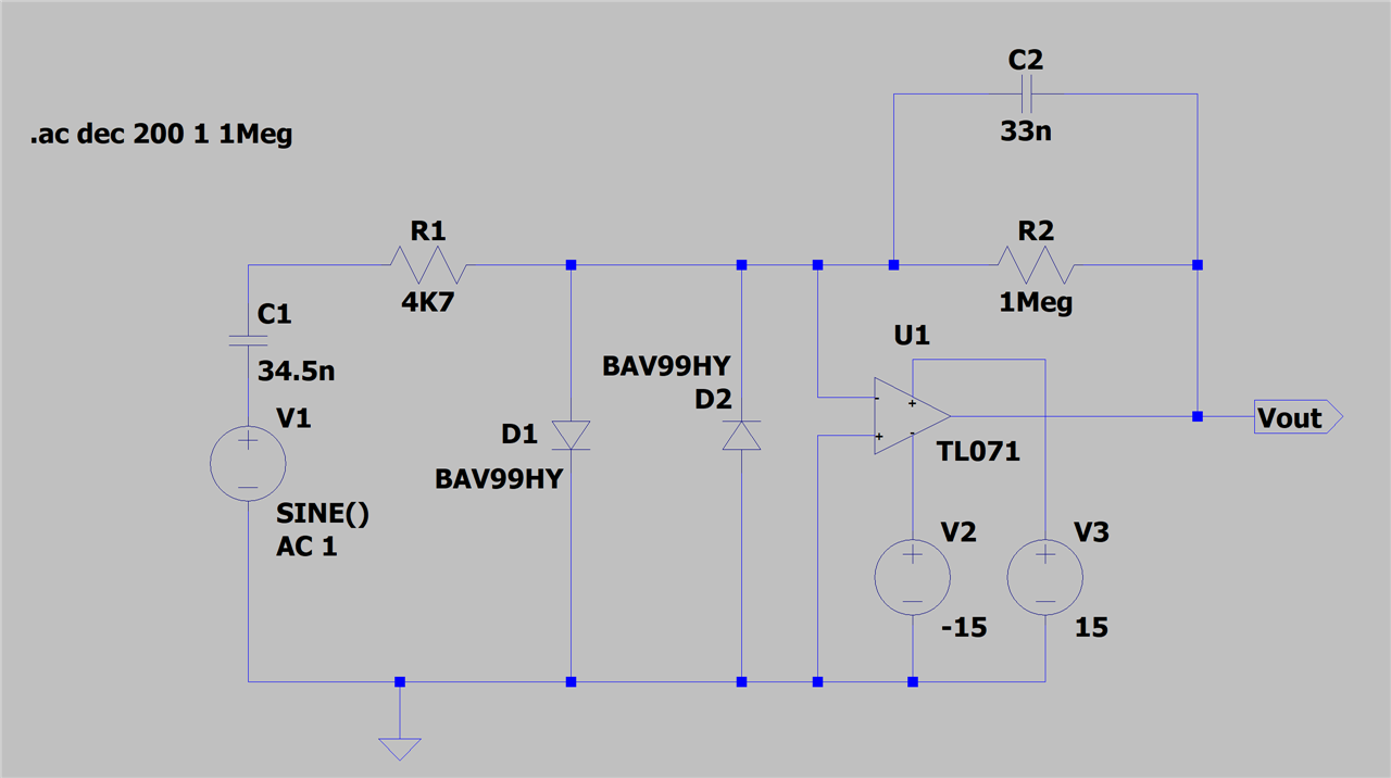
Michael designed a circuit that does both activities, and wrote a white paper about it. You can clearly see the two parts. Protection left, buffer right:

image

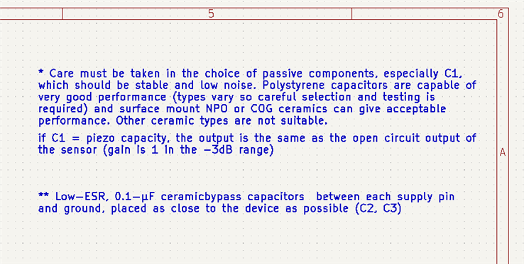
Two fast diodes keep the input under control, The buffer is a charge amp. To get 0dB (no gain), the capacitor in the feedback circuit should match the piezo element's capacity.

Simulation

LTSpice shows the amp's behaviour. The piezo element is replaced by a capacitor of the same value the piezo disk has (35 nF in my case, and an AC generator in serial.

image

Result:

image

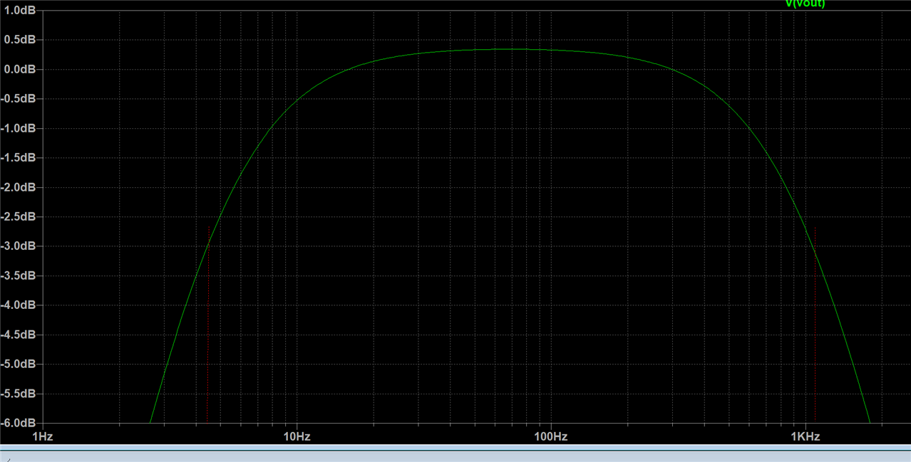
I did not simulate the crowbar function and high voltage input behaviour, but that's possible too.

Building the Circuit

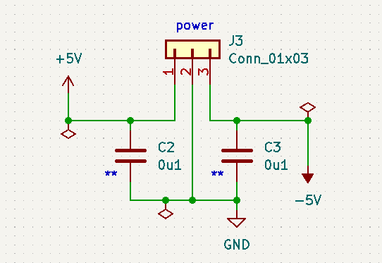
I designed a small PCB for this, in KiCAD. The main circuit is posted earlier in the blog. Here's additional circuitry, comments and the PCB design:

image image

image

BOM:

Vendor Vendor # type qty package mf mf code description url
farnell 3416403 C 1 1206 TDK CGA5F2C0G1H333J085AA SMD Multilayer Ceramic Capacitor, 0.033 µF, 50 V, 1206 [3216 Metric], ± 5%, C0G / NP0, CGA https://be.farnell.com/tdk/cga5f2c0g1h333j085aa/cap-aec-q200-0-033uf-50v-mlcc/dp/3416403?st=33nf%201206
farnell 1907339 C 2 1206 TDK C3216X7R2E104K160AA SMD Multilayer Ceramic Capacitor, 0.1 µF, 250 V, 1206 [3216 Metric], ± 10%, X7R, C https://be.farnell.com/tdk/c3216x7r2e104k160aa/cap-0-1-f-250v-10-x7r-1206/dp/1907339?st=c3216x7r2e104k160aa
farnell 2918843 D 1 SOT-23 ROHM BAV99HMT116 Small Signal Diode, Dual Series, 80 V, 125 mA, 1.25 V, 4 ns, 4 A https://be.farnell.com/rohm/bav99hmt116/diode-small-signal-0-125a-80v/dp/2918843?st=bav99hm
farnell 2447523 R 1 1206 MULTICOMP PRO MCWR12X4701FTL SMD Chip Resistor, 4.7 kohm, ± 1%, 250 mW, 1206 [3216 Metric], Thick Film, General Purpose https://be.farnell.com/multicomp/mcwr12x4701ftl/res-4k7-1-0-25w-1206-thick-film/dp/2447523?st=4k7%201206
farnell 2447478 R 1 1206 MULTICOMP PRO MCWR12X1004FTL SMD Chip Resistor, 1 Mohm, ± 1%, 250 mW, 1206 [3216 Metric], Thick Film, General Purpose https://be.farnell.com/multicomp/mcwr12x1004ftl/res-1m-1-0-25w-thick-film/dp/2447478?st=1m%20%201206
farnell 2849874 U 1 SOIC STMICROELECTRONICS TL071CDT Operational Amplifier, 1 Amplifier, 4 MHz, 16 V/µs, 6V to 36V, SOIC, 8 Pins https://be.farnell.com/stmicroelectronics/tl071cdt/so-08-15-jede-single-j-fet-op/dp/2849874?st=tl071

The built-up circuit:

image

Measurements and Use with a DAQ

Here's a scope capture when performing the same torture on the disk as in the first section: ticking it with a plastic pen:

image

This is good behaviour. The signal stays within the voltage rails. For my DAQ this is fine, because it has a 5VPP ac range. If you use a Pi, you'll have to add a little circuit to transform this into the 0 - 3.3VPP range.

This is the device in action:

You don't have permission to edit metadata of this video.
Edit media
x
image
Upload Preview
image

I then also mounted the industrial piezo accelerometer, and compared the signals in a LabVIEW flow I had made for the original DAQ road test:

image

Here are the results, showing that the piezo disk is capable of sensing vibrations. And that Michael's circuit delivers a useable output:

image

Channel 0 is the industrial accelerator, with its signal 3x attenuated compared to Channel 1, the piezo disk. I've also tried if the signal is good enough to detect acceleration and resonance frequency: yes

image

The frequency, in the FFT bottom of screen, is spot on. The acceleration works too, but note that this is not an accurate value, because I did not specify this device's voltage per gram.
I can specify it, using the industrial accelerometer as data point. That accelerator has this attribute documented (100 mV/g or 10.2 mV/s2).

LTSpice model: kellettdesign.zip

KiCAD project: piezo_charge_circuit_20220821.zip

Thank you for reading.

  • Sign in to reply

Top Comments

  • jc2048
    jc2048 over 2 years ago in reply to Jan Cumps +2
    Isn't the High-Z mode simply a change to the way the amplitude is set and reported? Doesn't your generator always have the 50R series termination in place (so the output impedance always looks like 50R…
  • Jan Cumps
    Jan Cumps 11 months ago

    michaelkellett , the charge amp white paper link throws a 404: not found error. Did it move?

    • Cancel
    • Vote Up 0 Vote Down
    • Sign in to reply
    • More
    • Cancel
  • Jan Cumps
    Jan Cumps over 2 years ago in reply to jc2048

    Isn't the High-Z mode simply a change to the way the amplitude is set and reported? Doesn't your generator always have the 50R series termination in place (so the output impedance always looks like 50R)? 

    Yes, like my other generators do too. I wasn't thinking clearly obviously Blush

    • Cancel
    • Vote Up 0 Vote Down
    • Sign in to reply
    • More
    • Cancel
  • jc2048
    jc2048 over 2 years ago in reply to Jan Cumps

    Isn't the High-Z mode simply a change to the way the amplitude is set and reported? Doesn't your generator always have the 50R series termination in place (so the output impedance always looks like 50R)? I think the mode refers to what's connected to the output, but I could be wrong.

    For your tests, a 33n in series with the generator as a simple electrical simulation of the disc looks fine to me (obviously it can't model all the mechanical resonances of a real disc). The generator's additional 50R doesn't make much difference - effectively it adds to the 4k7 and changes it by 1%, so probably no more effect than the tolerance of the resistors you used.

    • Cancel
    • Vote Up +2 Vote Down
    • Sign in to reply
    • More
    • Cancel
  • Jan Cumps
    Jan Cumps over 2 years ago in reply to Jan Cumps

    I will try the same now with the high-Z mode of the function generator. A piezo element is also a high-impedance component ...

    • Cancel
    • Vote Up 0 Vote Down
    • Sign in to reply
    • More
    • Cancel
  • Jan Cumps
    Jan Cumps over 2 years ago in reply to Jan Cumps

    I want to replace the piezo disk by a (programmable) function generator. To do tests across frequencies and amplitudes.

    • Do I calculate (maybe from the datasheet?) the impedance of my function generator? Then either put capacitors in series or parallel to match the impedance of the feedback capacitor?
    • Do I calculate that same value, then replace the cap in the feedback circuit with one that matches my test circuit? (and is that relevant?)

    This circuit is based on capacities - it's a charge amplifier - so I have to deal with capacitance.

    I tried this out. I'm using the power amp of my generator. It has an output impedance < 2Ω.

    I put a series capacitor of 33 nF at the input (similar as the LTSpice simulation setup above).

    image

    The function generator set to 200 mVRMS, 40 Hz. 

    Oscilloscope probes on input (before the capacitor) and at the output. Here's a capture:

    image

    • Cancel
    • Vote Up 0 Vote Down
    • Sign in to reply
    • More
    • Cancel
>
element14 Community

element14 is the first online community specifically for engineers. Connect with your peers and get expert answers to your questions.

  • Members
  • Learn
  • Technologies
  • Challenges & Projects
  • Products
  • Store
  • About Us
  • Feedback & Support
  • FAQs
  • Terms of Use
  • Privacy Policy
  • Legal and Copyright Notices
  • Sitemap
  • Cookies

An Avnet Company © 2025 Premier Farnell Limited. All Rights Reserved.

Premier Farnell Ltd, registered in England and Wales (no 00876412), registered office: Farnell House, Forge Lane, Leeds LS12 2NE.

ICP 备案号 10220084.

Follow element14

  • X
  • Facebook
  • linkedin
  • YouTube