element14 Community
element14 Community
    Register Log In
  • Site
  • Search
  • Log In Register
  • About Us
  • Community Hub
    Community Hub
    • What's New on element14
    • Feedback and Support
    • Benefits of Membership
    • Personal Blogs
    • Members Area
    • Achievement Levels
  • Learn
    Learn
    • Ask an Expert
    • eBooks
    • element14 presents
    • Learning Center
    • Tech Spotlight
    • STEM Academy
    • Webinars, Training and Events
    • Learning Groups
  • Technologies
    Technologies
    • 3D Printing
    • FPGA
    • Industrial Automation
    • Internet of Things
    • Power & Energy
    • Sensors
    • Technology Groups
  • Challenges & Projects
    Challenges & Projects
    • Design Challenges
    • element14 presents Projects
    • Project14
    • Arduino Projects
    • Raspberry Pi Projects
    • Project Groups
  • Products
    Products
    • Arduino
    • Avnet Boards Community
    • Dev Tools
    • Manufacturers
    • Multicomp Pro
    • Product Groups
    • Raspberry Pi
    • RoadTests & Reviews
  • Store
    Store
    • Visit Your Store
    • Choose another store...
      • Europe
      •  Austria (German)
      •  Belgium (Dutch, French)
      •  Bulgaria (Bulgarian)
      •  Czech Republic (Czech)
      •  Denmark (Danish)
      •  Estonia (Estonian)
      •  Finland (Finnish)
      •  France (French)
      •  Germany (German)
      •  Hungary (Hungarian)
      •  Ireland
      •  Israel
      •  Italy (Italian)
      •  Latvia (Latvian)
      •  
      •  Lithuania (Lithuanian)
      •  Netherlands (Dutch)
      •  Norway (Norwegian)
      •  Poland (Polish)
      •  Portugal (Portuguese)
      •  Romania (Romanian)
      •  Russia (Russian)
      •  Slovakia (Slovak)
      •  Slovenia (Slovenian)
      •  Spain (Spanish)
      •  Sweden (Swedish)
      •  Switzerland(German, French)
      •  Turkey (Turkish)
      •  United Kingdom
      • Asia Pacific
      •  Australia
      •  China
      •  Hong Kong
      •  India
      •  Korea (Korean)
      •  Malaysia
      •  New Zealand
      •  Philippines
      •  Singapore
      •  Taiwan
      •  Thailand (Thai)
      • Americas
      •  Brazil (Portuguese)
      •  Canada
      •  Mexico (Spanish)
      •  United States
      Can't find the country/region you're looking for? Visit our export site or find a local distributor.
  • Translate
  • Profile
  • Settings
Test Instrumentation
  • Challenges & Projects
  • Project14
  • Test Instrumentation
  • More
  • Cancel
Test Instrumentation
Blog Project PITS Soft Latch Circuits
  • Blog
  • Forum
  • Documents
  • Events
  • Polls
  • Files
  • Members
  • Mentions
  • Sub-Groups
  • Tags
  • More
  • Cancel
  • New
Join Test Instrumentation to participate - click to join for free!
  • Share
  • More
  • Cancel
Group Actions
  • Group RSS
  • More
  • Cancel
Engagement
  • Author Author: three-phase
  • Date Created: 17 Dec 2018 9:38 PM Date Created
  • Views 2396 views
  • Likes 6 likes
  • Comments 3 comments
  • soft latch
  • diytestinstruch
Related
Recommended

Project PITS Soft Latch Circuits

three-phase
three-phase
17 Dec 2018
image

Test Instrumentation

Enter Your Electronics & Design Project for a chance to win a Grand Prize for Originality, a Tool Set, and a $100 Shopping Cart!

Back to The Project14 homepage image

Project14 Home
Monthly Themes
Monthly Theme Poll


I have been playing around with the soft latch circuit that enables PITS to be turned on / off with a single non-latching switch. I had problems getting the original circuit to work correctly on the breadboard.


image


A discussion regarding the soft latch circuit in Project PITS update blog, and genebren provided an alternative circuit for me to investigate.


image

Whilst wiring up this alternative circuit, I found out that I had a silly moment and identified the termination of the NPN transistor incorrectly and had swapped over the collector and emitter. In the photo below, I have crossed out the incorrect terminal markings and written in the correct ones.


image


With the circuit rebuilt with the transistors wired in correctly, the original circuit now functions correctly and will turn both on and off. So I decided to do a comparison between the two circuits, the logical placed seemed to be to start with a comparison of the BOMs. As can be seen in the table below, the original circuit uses 10 components and the alternative 11. However, the alternative circuit can be built slightly cheaper than the original circuit.


image


For both circuits, I measured operating current in three different states and the operating times for different options of each of the circuits.


image


image


It was noted that the alternative circuit drew slightly less current than the original circuit, the alternative circuit also dropped to the minimal current within a second of turning off, where as the original circuit took over 10 seconds for the current to drop from around 5.1uA to the 0.02uA.


imageimage


The alternative circuit originally took 7 seconds for the circuit voltage to drop down to zero, this time was reduced down to 2 seconds by reducing the 4.7uF capacitor down to 1uF. Although to be honest, for my application, I don't think the slow voltage turn off is any issue at all.


image

One problem I did have with the alternative circuit, that I have not resolved yet, was that it would not shutdown when the input voltage was less than 3.8V, which could be a problem for me given that I intend to power the circuit from an 18650 cell.


I also looked at modified circuits for the original circuit after reading through the comments on the EEVBlog.


image

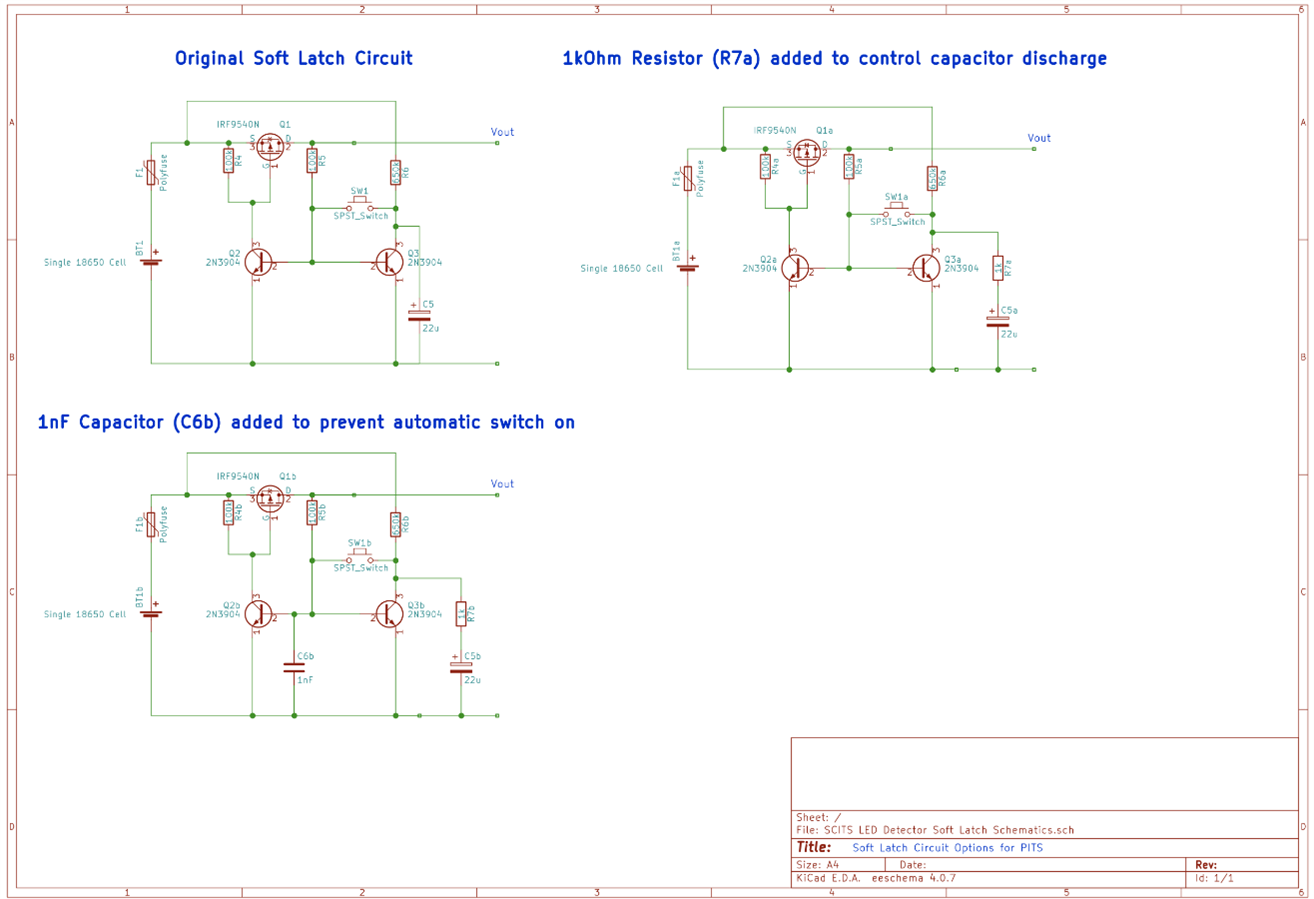
The first modification was to add a resistor between the capacitor and the collector of the the second transistor to reduce the current surge into the transistor base when the switch was closed.


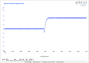
The second modification was to add a 1nF capacitor to the transistor bases from ground. This was done to prevent the circuit from automatically turning on when power is first applied. I personally didn't have an issue with this, but I did also notice that the negative spike during start up was removed when this capacitor was fitted.


imageimage

image


Due to the issue surrounding the low battery voltage on the alternative circuit, I will stick to the original soft latch circuit. This leaves me with the PCB to modify to correct the original mistake and add in the two extra components.

  • Sign in to reply

Top Comments

  • genebren
    genebren over 6 years ago +2
    Donald, Well done on finding the problem with the initial circuit and also for doing a great comparison of the characteristics of the two circuits. You could like correct the shutdown issue of the second…
  • three-phase
    three-phase over 6 years ago in reply to genebren +2
    Thanks for your help with this Gene, much appreciated. The MOSFET you have suggested looks ideal, the circuit will only draw around 10mA when triggered, so no heavy current drain at all. Given my lack…
  • genebren
    genebren over 6 years ago +2
    Donald, Trying out the MOSFET before re-spining the PCB is a great idea. You might be able to tack the new part onto your existing PCB. Good luck! Gene
Parents
  • genebren
    genebren over 6 years ago

    Donald,


    Well done on finding the problem with the initial circuit and also for doing a great comparison of the characteristics of the two circuits.  You could like correct the shutdown issue of the second circuit by using a MOSFET with a lower Vgs, like FDN340PCT-ND https://www.newark.com/search?st=FDN340PCT-ND  .  This part would likely work in either circuit and it is a cheaper and likely a closer match to your needs (the IRF9540 is a pretty hefty MOSFET for a Li-ion circuit, unless you plan on very high currents).


    Best of luck!

    Gene

    • Cancel
    • Vote Up +2 Vote Down
    • Sign in to reply
    • More
    • Cancel
Comment
  • genebren
    genebren over 6 years ago

    Donald,


    Well done on finding the problem with the initial circuit and also for doing a great comparison of the characteristics of the two circuits.  You could like correct the shutdown issue of the second circuit by using a MOSFET with a lower Vgs, like FDN340PCT-ND https://www.newark.com/search?st=FDN340PCT-ND  .  This part would likely work in either circuit and it is a cheaper and likely a closer match to your needs (the IRF9540 is a pretty hefty MOSFET for a Li-ion circuit, unless you plan on very high currents).


    Best of luck!

    Gene

    • Cancel
    • Vote Up +2 Vote Down
    • Sign in to reply
    • More
    • Cancel
Children
  • three-phase
    three-phase over 6 years ago in reply to genebren

    Thanks for your help with this Gene, much appreciated. The MOSFET you have suggested looks ideal, the circuit will only draw around 10mA when triggered, so no heavy current drain at all.


    Given my lack of knowledge in these things though, I would prefer to try out the MOSFET before committing to the PCB being made.


    Looks like the device is also available in Farnell UK, FDN340, sometimes they aren't available and there is a surcharge for delivery from America, which generally negates at cost improvements.


    Kind regards.

    • Cancel
    • Vote Up +2 Vote Down
    • Sign in to reply
    • More
    • Cancel
element14 Community

element14 is the first online community specifically for engineers. Connect with your peers and get expert answers to your questions.

  • Members
  • Learn
  • Technologies
  • Challenges & Projects
  • Products
  • Store
  • About Us
  • Feedback & Support
  • FAQs
  • Terms of Use
  • Privacy Policy
  • Legal and Copyright Notices
  • Sitemap
  • Cookies

An Avnet Company © 2025 Premier Farnell Limited. All Rights Reserved.

Premier Farnell Ltd, registered in England and Wales (no 00876412), registered office: Farnell House, Forge Lane, Leeds LS12 2NE.

ICP 备案号 10220084.

Follow element14

  • X
  • Facebook
  • linkedin
  • YouTube