element14 Community
element14 Community
    Register Log In
  • Site
  • Search
  • Log In Register
  • About Us
  • Community Hub
    Community Hub
    • What's New on element14
    • Feedback and Support
    • Benefits of Membership
    • Personal Blogs
    • Members Area
    • Achievement Levels
  • Learn
    Learn
    • Ask an Expert
    • eBooks
    • element14 presents
    • Learning Center
    • Tech Spotlight
    • STEM Academy
    • Webinars, Training and Events
    • Learning Groups
  • Technologies
    Technologies
    • 3D Printing
    • FPGA
    • Industrial Automation
    • Internet of Things
    • Power & Energy
    • Sensors
    • Technology Groups
  • Challenges & Projects
    Challenges & Projects
    • Design Challenges
    • element14 presents Projects
    • Project14
    • Arduino Projects
    • Raspberry Pi Projects
    • Project Groups
  • Products
    Products
    • Arduino
    • Avnet Boards Community
    • Dev Tools
    • Manufacturers
    • Multicomp Pro
    • Product Groups
    • Raspberry Pi
    • RoadTests & Reviews
  • Store
    Store
    • Visit Your Store
    • Choose another store...
      • Europe
      •  Austria (German)
      •  Belgium (Dutch, French)
      •  Bulgaria (Bulgarian)
      •  Czech Republic (Czech)
      •  Denmark (Danish)
      •  Estonia (Estonian)
      •  Finland (Finnish)
      •  France (French)
      •  Germany (German)
      •  Hungary (Hungarian)
      •  Ireland
      •  Israel
      •  Italy (Italian)
      •  Latvia (Latvian)
      •  
      •  Lithuania (Lithuanian)
      •  Netherlands (Dutch)
      •  Norway (Norwegian)
      •  Poland (Polish)
      •  Portugal (Portuguese)
      •  Romania (Romanian)
      •  Russia (Russian)
      •  Slovakia (Slovak)
      •  Slovenia (Slovenian)
      •  Spain (Spanish)
      •  Sweden (Swedish)
      •  Switzerland(German, French)
      •  Turkey (Turkish)
      •  United Kingdom
      • Asia Pacific
      •  Australia
      •  China
      •  Hong Kong
      •  India
      •  Korea (Korean)
      •  Malaysia
      •  New Zealand
      •  Philippines
      •  Singapore
      •  Taiwan
      •  Thailand (Thai)
      • Americas
      •  Brazil (Portuguese)
      •  Canada
      •  Mexico (Spanish)
      •  United States
      Can't find the country/region you're looking for? Visit our export site or find a local distributor.
  • Translate
  • Profile
  • Settings
Test Instrumentation
  • Challenges & Projects
  • Project14
  • Test Instrumentation
  • More
  • Cancel
Test Instrumentation
Forum Project PITS Problem
  • Blog
  • Forum
  • Documents
  • Events
  • Polls
  • Files
  • Members
  • Mentions
  • Sub-Groups
  • Tags
  • More
  • Cancel
  • New
Join Test Instrumentation to participate - click to join for free!
Actions
  • Share
  • More
  • Cancel
Forum Thread Details
  • State Verified Answer
  • Replies 18 replies
  • Answers 10 answers
  • Subscribers 19 subscribers
  • Views 3020 views
  • Users 0 members are here
  • current pickup
  • comparator
  • scits
Related

Project PITS Problem

three-phase
three-phase over 6 years ago

I have been trying to build up a Pick-up Indicator Test System (PITS) to detect the overcurrent indicator on protection relays I test, for the project14 test instrumentation.


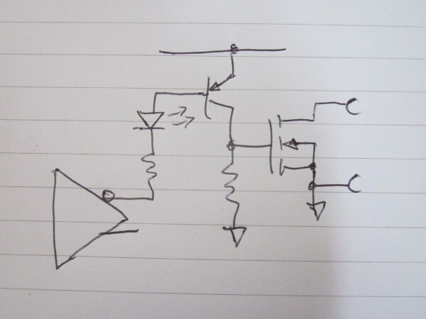
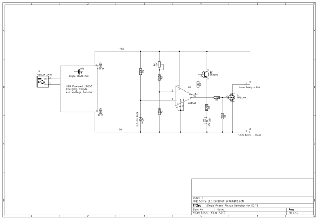
Once  I figured out that there are some photo diodes that respond better to green LEDs than others, I managed to get the circuit working. However, I then decided to add an output indicator off the negated output of the AD8561 comparator chip I was using. After adding this, both outputs of the comparator remain low and the LED is on all of the time.


When I drop out R6, the 10k resistor to the pnp transistor base, the circuit starts to work again.


Anybody have any ideas what I am doing wrong? The only thing I can think of doing is to increase the size of R6, I had originally calculated this as 14k for a 1mA base current, but from my limited selection, 10k was the closest I had.


I also find that when turned on, the MOSFET has a resistance of 780 ohms, which seems a little high to me?


image


image


Kind regards

  • Sign in to reply
  • Cancel

Top Replies

  • jc2048
    jc2048 over 6 years ago +9 verified
    Your transistor is upside down - you've got the collector and emitter swapped. A transistor will work like that, but the gain is very much less than if you use it the right way round so you'd only ever…
  • Dudley
    Dudley over 6 years ago in reply to dougw +5 suggested
    better now?
  • three-phase
    three-phase over 6 years ago in reply to 14rhb +4 suggested
    Hello Rod, Many thanks for your help. I have read through the data sheet for the AD8561 and it does not say much about the outputs and if they are differential or inverse from one another. I have just…
  • 14rhb
    0 14rhb over 6 years ago

    Hi Donald,


    [I could be completely wrong...]

    I wonder if those outputs are differential rather that just a plain inverse of each other. By taking one to your PNP you are pushing the feed to your MOSFET below any possibility of turning it on (as the difference between them is not changed) ?


    The gate resistor to ground on your MOSFET is just to ensure it turns off, I'd make that a bit bigger e.g maybe 100k to 1M. This would make your Vgs higher and make it conduct better (lower Rds).


    Have you tried using a NPN off the main output to drive your LED?


    Rod

    • Cancel
    • Vote Up +3 Vote Down
    • Sign in to reply
    • Verify Answer
    • Reject Answer
    • Cancel
  • three-phase
    0 three-phase over 6 years ago in reply to 14rhb

    Hello Rod,


    Many thanks for your help.


    I have read through the data sheet for the AD8561 and it does not say much about the outputs and if they are differential or inverse from one another.


    I have just replaced, the 10k pull down resistor with a 300k one and the MOSFET now goes down to 30 ohms when switched on.


    The output voltages are as follows with a supply voltage of 4.52V


    Comparator off - Pin 7 is at 0.188V and Pin 8 at 3.86V

    Comparator on - Pin 7 is at 3.30V and Pin 8 at 0.190V


    These were measured with R6 still removed.


    I have not tried an NPN transistor. I did not want to run that in parallel with the MOSFET gate in case it affected its operation. I will have a look and see what is in my box of bits and see if I can find a bigger resistor for the gate.


    Kind regards

    • Cancel
    • Vote Up +4 Vote Down
    • Sign in to reply
    • Verify Answer
    • Reject Answer
    • Cancel
  • dougw
    0 dougw over 6 years ago

    Dudley  I cannot see the images...they are "unauthorized" in both Chrome and IE.

    • Cancel
    • Vote Up +3 Vote Down
    • Sign in to reply
    • Verify Answer
    • Cancel
  • 14rhb
    0 14rhb over 6 years ago in reply to three-phase

    Hi Donald,


    You are more than welcome. Sounds like you are making headway - which is always good to hear.


    I'm not sure how you intend to use the output 4mm or how much current you want out; is 30 ohms a low enough resistance? I looked up the MOSFET you are using and the device conducts completely when Vgs is 10v, although the Vgs threshold is 2-4V. You could perhaps find a device that saturates at a lower Vgs ? There seems to be a handful of MOSFETS that have much lower "Rds(on) Test Voltage Vgs" which is a parameter you can select and filter via on the Farnell/Newark website...but most devices seem to be SMT image


    I think you should be all right taking the transistor and MOSFET off the same output. The MOSFET gate will be high impedance so won't affect the output. The transistor will be fed via its base resistor to derive the base current. [Famous last words image]


    Nice Veroboard layout by the way.


    Rod

    • Cancel
    • Vote Up +3 Vote Down
    • Sign in to reply
    • Verify Answer
    • Reject Answer
    • Cancel
  • Dudley
    0 Dudley over 6 years ago in reply to dougw

    better now?

    • Cancel
    • Vote Up +5 Vote Down
    • Sign in to reply
    • Verify Answer
    • Reject Answer
    • Cancel
  • 14rhb
    0 14rhb over 6 years ago in reply to dougw

    I should have said, Donald's schematic didn't open for me either (Firefox/Windows10) but I zoomed my browser to see the details instead.


    Rod

    • Cancel
    • Vote Up +2 Vote Down
    • Sign in to reply
    • Verify Answer
    • Cancel
  • jc2048
    0 jc2048 over 6 years ago

    Your transistor is upside down - you've got the collector and emitter swapped. A transistor will work like that, but the gain is very much less than if you use it the right way round so you'd only ever do it in a circuit if you specifically wanted the very low saturation voltage it gives [in the old days, people used to build chopper amplifiers with transistors in 'inverse mode' for that reason].


    The comparator outputs are designed to drive TTL inputs where the threshold would be around 1.5V and the high output only needs to be (at least) 2.8V.


    If you've got a high-brightness white, green or blue LED, where the forward voltage would be a little over 3V and it would illuminate on a couple of milliamps, you could consider something like this


    image


    The comparator is very fast. Make sure you have the decoupling they recommend, close in to the part's supply pins, and be careful with the layout. You might also want some hysteresis - the input will only move slowly when there's no photodiode current [the reverse capacitance of the diode is quite high and there's only 5M to charge it], so when you slowly transition past the switching point there's a real possibility that noise will cause the output to chatter.

    • Cancel
    • Vote Up +9 Vote Down
    • Sign in to reply
    • Verify Answer
    • Reject Answer
    • Cancel
  • three-phase
    0 three-phase over 6 years ago in reply to 14rhb

    The photo is a jpeg but the schematic was saved as a png - maybe that is the reason?


    Kind regards

    • Cancel
    • Vote Up +1 Vote Down
    • Sign in to reply
    • Verify Answer
    • Reject Answer
    • Cancel
  • three-phase
    0 three-phase over 6 years ago in reply to 14rhb

    The 4mm output jacks will connect into the timing circuit of an injection test set, very low current but the voltage from the test set can vary depending on its setup or the the of tester used and I wanted to keep the circuit usable on as many testers as possible.


    I will try an npn transistor over the weekend and see what happens.


    Thanks for the help.

    • Cancel
    • Vote Up +2 Vote Down
    • Sign in to reply
    • Verify Answer
    • Reject Answer
    • Cancel
  • three-phase
    0 three-phase over 6 years ago in reply to jc2048

    Many thanks for the information, I believe the led I fitted was high intensity so I can look to rework the circuit and get the transistor connected the correct way around.


    The circuit shouldn't transition slowly. The photodiode will sit enclosed over an LED on the protection relay and conducts when that LED is lit. I haven't noticed any chatter whilst testing the circuit.


    Unfortunately, I haven't given all the details of how it will be used, so you wouldn't have known any of this.


    Kind regards.

    • Cancel
    • Vote Up +3 Vote Down
    • Sign in to reply
    • Verify Answer
    • Reject Answer
    • Cancel
>
element14 Community

element14 is the first online community specifically for engineers. Connect with your peers and get expert answers to your questions.

  • Members
  • Learn
  • Technologies
  • Challenges & Projects
  • Products
  • Store
  • About Us
  • Feedback & Support
  • FAQs
  • Terms of Use
  • Privacy Policy
  • Legal and Copyright Notices
  • Sitemap
  • Cookies

An Avnet Company © 2025 Premier Farnell Limited. All Rights Reserved.

Premier Farnell Ltd, registered in England and Wales (no 00876412), registered office: Farnell House, Forge Lane, Leeds LS12 2NE.

ICP 备案号 10220084.

Follow element14

  • X
  • Facebook
  • linkedin
  • YouTube