element14 Community
element14 Community
    Register Log In
  • Site
  • Search
  • Log In Register
  • About Us
  • Community Hub
    Community Hub
    • What's New on element14
    • Feedback and Support
    • Benefits of Membership
    • Personal Blogs
    • Members Area
    • Achievement Levels
  • Learn
    Learn
    • Ask an Expert
    • eBooks
    • element14 presents
    • Learning Center
    • Tech Spotlight
    • STEM Academy
    • Webinars, Training and Events
    • Learning Groups
  • Technologies
    Technologies
    • 3D Printing
    • FPGA
    • Industrial Automation
    • Internet of Things
    • Power & Energy
    • Sensors
    • Technology Groups
  • Challenges & Projects
    Challenges & Projects
    • Design Challenges
    • element14 presents Projects
    • Project14
    • Arduino Projects
    • Raspberry Pi Projects
    • Project Groups
  • Products
    Products
    • Arduino
    • Avnet Boards Community
    • Dev Tools
    • Manufacturers
    • Multicomp Pro
    • Product Groups
    • Raspberry Pi
    • RoadTests & Reviews
  • Store
    Store
    • Visit Your Store
    • Choose another store...
      • Europe
      •  Austria (German)
      •  Belgium (Dutch, French)
      •  Bulgaria (Bulgarian)
      •  Czech Republic (Czech)
      •  Denmark (Danish)
      •  Estonia (Estonian)
      •  Finland (Finnish)
      •  France (French)
      •  Germany (German)
      •  Hungary (Hungarian)
      •  Ireland
      •  Israel
      •  Italy (Italian)
      •  Latvia (Latvian)
      •  
      •  Lithuania (Lithuanian)
      •  Netherlands (Dutch)
      •  Norway (Norwegian)
      •  Poland (Polish)
      •  Portugal (Portuguese)
      •  Romania (Romanian)
      •  Russia (Russian)
      •  Slovakia (Slovak)
      •  Slovenia (Slovenian)
      •  Spain (Spanish)
      •  Sweden (Swedish)
      •  Switzerland(German, French)
      •  Turkey (Turkish)
      •  United Kingdom
      • Asia Pacific
      •  Australia
      •  China
      •  Hong Kong
      •  India
      •  Korea (Korean)
      •  Malaysia
      •  New Zealand
      •  Philippines
      •  Singapore
      •  Taiwan
      •  Thailand (Thai)
      • Americas
      •  Brazil (Portuguese)
      •  Canada
      •  Mexico (Spanish)
      •  United States
      Can't find the country/region you're looking for? Visit our export site or find a local distributor.
  • Translate
  • Profile
  • Settings
Holiday Special 19
  • Challenges & Projects
  • Project14
  • Holiday Special 19
  • More
  • Cancel
Holiday Special 19
Blog Touch of Love
  • Blog
  • Forum
  • Documents
  • Events
  • Polls
  • Files
  • Members
  • Mentions
  • Sub-Groups
  • Tags
  • More
  • Cancel
  • New
Join Holiday Special 19 to participate - click to join for free!
  • Share
  • More
  • Cancel
Group Actions
  • Group RSS
  • More
  • Cancel
Engagement
  • Author Author: ptoth
  • Date Created: 31 Dec 2019 1:42 PM Date Created
  • Views 1977 views
  • Likes 14 likes
  • Comments 9 comments
  • holidayspecial19ch
Related
Recommended

Touch of Love

ptoth
ptoth
31 Dec 2019

Hello folks,


As my this year's Holiday Special Project I thought it would be interesting to visualize the warmth feelings spread during the Christmas days. Therefore, feel welcome to meet my project "Touch of Love"


No matter if you want to conjure a smile on the lips of your partner or close-ones, with this gadget, you will have success. And the best part, you only need a few components and minimal soldering skills. Throughout this blog post, I will describe the circuit. First, from a general concept and then getting more and more detailed with each step. The passages next to the schematic contain more information regarding the design procedure and are good to know if you want to rebuild the circuit or modify it slightly. If this is not your intention, just skip them. Alright, enough talking, let's start...


As always, at the beginning of a project, there is some kind of vision of the end product. The below animation visualize this.

image

Fig 1. Touch of Love Animation.

Credits to tenor and StefaniaDAngeli for base animation.


General Description

So the basic idea is to have a circuit that is going to react to any kind of body contact with the one whom you want to bring to smile or whom you want to show the strong bond between yourselves. From this point, we can deduce three states of the circuit:

  • Off - since this is a battery-powered circuit, a switch is used to turn the gadget on and off.
  • State 1 - After turning on the circuit we enter State 1
  • State 2 - Is triggered by body contact and transits automatically back to State 1 once the two persons do not touch anymore.

Having this general functional description, the next step is to give State 1 and 2 a more detailed description and to create a circuit that fulfills the correct state transitions.
I decided to use eight LEDs as a visual actuator which are turned on slightly in State 1 and are boosted with more current in State 2, resulting in a brighter glow.


Circuit Schematics

The circuit schematic is shown below:

image


Let's investigate the circuit in a bit more detail.
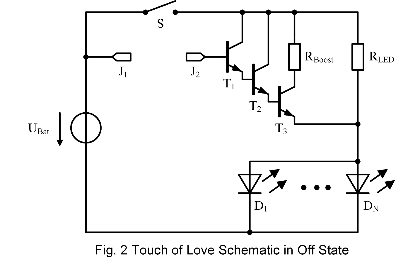
The on/off switch S triggers the transition between the off State and State 1. Once the circuit is turned on, the default State 1 is entered and all LEDs are glowing slightly. The voltage supply (battery) is small in volume so an overall compact design can be realized. It is a coin battery with UBAT=3V.


For the description of State 1, let's focus on the below schematic with the active components marked in black.

   
image

As mentioned above all LEDs are glowing slightly. The glow is adjusted mainly by the resistance RLED. Choosing an appropriate value is affected by the color and amount of LEDs.

Detailed Design Description:
To calculate the size of RLED, we need to determine two values the current IRLED and voltage drop across the LED URLED.
IRLED depends on the type, color and amount of the LEDs. In my case, I used N=8 red LEDs with ILED=5mA at full brightness and IGlow=1mA. This means N LEDs in parallel require IRLED=N*IGlow=8mA for a slight glow.
Moreover, the LED forward voltage is ULED=2V. With this and the Kirchhoffs loop equation, we can calculate the remaining voltage drop over the resistance with URLED=UBAT-ULED = 1V. With Ohms law, we can compute a resistance of RLED=URLED/IRLED=1V/8mA = 125 Ohm.
Above explanation in short form:  RLED=(UBAT-ULED)/(N*IGlow)

Sidenote 1: The parallel connection is suitable for low voltage supplies and, therefore a compact gadget design because the number of batteries required is held low. Modifying the number of LEDs or the color requires only a change in the small resistance rather than a change in the bulky power supply.


Now that we investigated the circuitry responsible for the default glow lets have a look at the brightness boosting circuit.


image

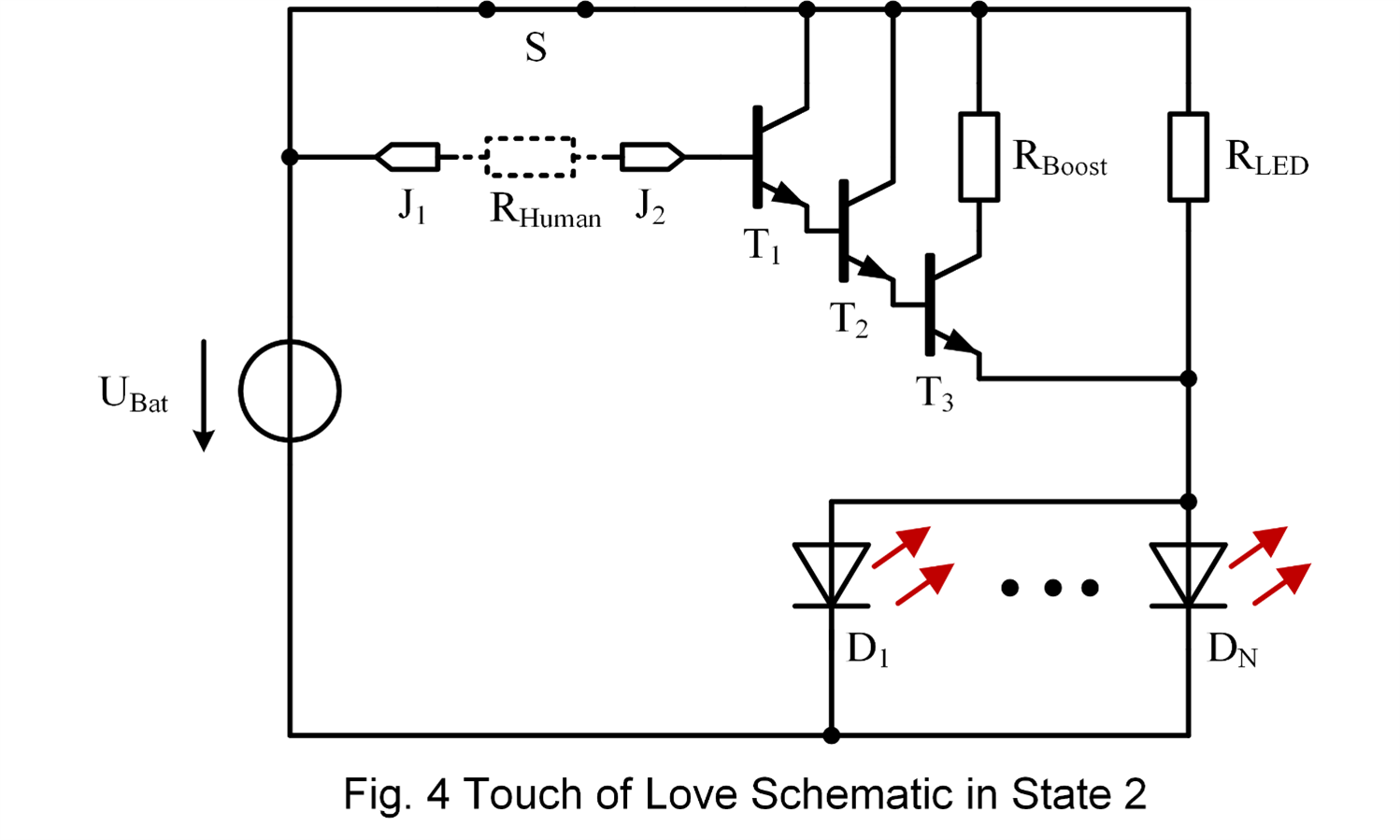
The idea behind the applied circuit is to increase IRLED by creating a second path for the current to flow. In the simplest version, you could do this by using a push-button in parallel to the resistance. Once the button is pushed the resistance, RLED is changed and the LEDs glow brighter. However, in this gadget, the switch should be replaced by body contact. As shown in the schematic, the body contact can be modeled with a very high resistance approximately a few mega Ohm. Such a high resistance conducts only a tiny amount of current which, applied directly to the LEDs, would not be enough to create a visible change. Therefore we need to amplify the current. This task is performed by the bipolar transistors T1-T3. Each stage is increasing the tiny current flow at the base of T1. Until a second LED current path is created at the collector-emitter of T3. The resistance RGlow is used to adjust the brightness boost.

Sidenote 1: Using bipolar transistors with a high amplification factor or Darlington transistors could cut down the number of components even more.

Sidenote 2: Using MOSFET instead of bipolar would be feasible as well, but because of the floating high impedance input at the first stage, the circuit becomes very sensitive to nearby electric fields. In other words, getting close to the gadget may already trigger the circuit, which in this application is not intended.
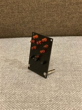


Assembly

Enough theory for now, the assembly was done with the above components on a PCB prototype breadboard. First, I attached the LEDs and transistors in the desired shape and used the “legs” for connection. Afterwards, I soldered the two SMD transistors to the bottom side and added the switch. An old computer motherboard gave me, with a bit desoldering effort, a coin cell battery holder which I also attached to the bottom side of the PCB. Finally, two screw extensions are used to form a stable standing at the same time J1 and J2 for the touch response.
In the end, I used black paint to give a nice finish and insulate the bare wires on the back.

imageimageimage


Conclusion

The result is shown in the video below. As already described at the top the circuit has a large smile factor. As the first “victim” I choose my girlfriend. First I switched it on and got the standard “Oh…” but when I told her to hold one side (while holding the other side myself) and put my hand into mine her eyes turned big “Woooow how is this working?!?!”image image


You don't have permission to edit metadata of this video.
Edit media
x
image
Upload Preview
image


Have a happy new Year image

  • Sign in to reply

Top Comments

  • jw0752
    jw0752 over 5 years ago +3
    Really cute. You will have to resubmit this one for Valentines Day. John
  • DAB
    DAB over 5 years ago +2
    Nice and useful project. DAB
  • dubbie
    dubbie over 5 years ago +1
    An innovative construction from parts and components you already had. Impressive. Dubbie
  • ptoth
    ptoth over 5 years ago in reply to elquike89

    Did you try different resistance values?
    Try to build it first on the bread board.


    full brightness  without even touching?

    build the circuit first without transistors and set the brightness to your needs, afterwards add stages one by one.

    • Cancel
    • Vote Up +1 Vote Down
    • Sign in to reply
    • More
    • Cancel
  • elquike89
    elquike89 over 5 years ago

    Hello, I couldn't get this to work, the leds always have full brightness on first state, i used 2n2222a

    • Cancel
    • Vote Up 0 Vote Down
    • Sign in to reply
    • More
    • Cancel
  • ptoth
    ptoth over 5 years ago in reply to helliossun

    Try to use a higher value transistor first and then decrease the value to gain more effect. It depends also on your LED color hence U_LED. Check the datasheet of the BC547 for the curves with I_C depending on U_CE.

    R_boost will limit the voltage over collector emitter and thus reduce the current I_C.

    • Cancel
    • Vote Up 0 Vote Down
    • Sign in to reply
    • More
    • Cancel
  • ptoth
    ptoth over 5 years ago in reply to ge1ge

    thanks for your, comment!

    Indeed having no R_LED would eliminate the effect of the amplification circuit in case of only battery supply since the BE diode is not biased enough. But this is not the case in the final setup. Also amplification starts before 0.7V BE.

    So choosing LED with a minimal forward voltage and accordingly a higher R_LED gives more room for current boosting. Furthermore reducing the amplification circuit to only two stages may be also a feasible solution to reduce the cascaded BE voltages. The trade off in this case is the amplification factor which might be compensated by transistors with a higher per stage amplification.

    Another possibility would be to use germanium transistors with U_BE = 0.3V.


    The reason for flickering is however interesting. The visible flickering in the video ocures when the right side is touched, which is the open base of the first stage. I doubt that ac coupling changes the base current so significantly. Using mosfet transistors I would agree as (Fig. 4 Sidnote 2) but bipolar transistors are current steered. It might be a random touch resistance change while holding, I am not sure.

    • Cancel
    • Vote Up +1 Vote Down
    • Sign in to reply
    • More
    • Cancel
  • ge1ge
    ge1ge over 5 years ago

    when you will use your fig 4 with short connection of the resistor, it will not work!

    Because you have 3 BE in series with 3*0.7V=2.1V. But you have only 3V Batterie, so 3V-2.1V=0.9V is on LED, when you have no R_LED.


    Why it is working in your case with your girlfriend?

    Because you are acting like antennas for your 220V (50Hz) or 110V (60Hz).

    So you have addition AC-Voltage with more then 1.1V peak. So you have a peak of 4.1V there and at the LED are more then 2V.

    Because of this in the video the LED is not constant lightning

    • Cancel
    • Vote Up +1 Vote Down
    • Sign in to reply
    • More
    • Cancel
>
element14 Community

element14 is the first online community specifically for engineers. Connect with your peers and get expert answers to your questions.

  • Members
  • Learn
  • Technologies
  • Challenges & Projects
  • Products
  • Store
  • About Us
  • Feedback & Support
  • FAQs
  • Terms of Use
  • Privacy Policy
  • Legal and Copyright Notices
  • Sitemap
  • Cookies

An Avnet Company © 2025 Premier Farnell Limited. All Rights Reserved.

Premier Farnell Ltd, registered in England and Wales (no 00876412), registered office: Farnell House, Forge Lane, Leeds LS12 2NE.

ICP 备案号 10220084.

Follow element14

  • X
  • Facebook
  • linkedin
  • YouTube