

Table of contents

Abstract
A GPS / Galileo / BeiDou / GLONASS receiver for Arduino using ST's Teseo III technology. This project covers how navigation systems work, and how to connect a GPS module, antenna, and extract timing, location, altitude and satellite information.
Project
Introduction
I’ve never built anything GNSS or Global Positioning System (GPS)-related before, but decided to give it a go. This blog post documents what I discovered!

How Does it Work?
There are well over a hundred satellites in orbit, which transmit signals containing timing information and satellite position. The timing information comes from an ultra-precise clock inside each satellite. For the satellite position, imagine a sphere surrounding the planet. The position can be defined as an angle from one of the poles, and the angle around the planet (for instance around the equator), which meet up at the satellite location on that sphere.
The information is transmitted at a frequency of about 1.5 GHz, and, due to the distance of the satellite orbit, it takes about 10 msec to arrive on Earth.
The received signal is very weak, and would be impossible to pull out of the noise, so it is sent relatively slowly (50 bits per second), with each bit of data being encoded with a special (much faster) binary pattern before it’s transmitted. The GPS receiver tries to match up the pattern. When it does that, then, mathematically, the signal can be recovered from the noise; the pattern is known as a pseudo-random sequence (although it contains the word ‘random’, it’s not random in the normal sense; it looks random to a casual viewer, but in reality it has a pattern that can be exactly replicated by the receiver), and the matching effect is known as autocorrelation. Together, it is known as Spread Spectrum communication. It’s pretty amazing, because it’s invisible on a spectrum analyzer (since it’s below the noise floor!) until autocorrelation is achieved by the receiving system.
Another neat trick is that many satellites can transmit simultaneously, each with a different pseudo-random sequence, and the receiver can, in parallel, perform multiple matching operations, to achieve autocorrelation for each signal.
The receiver is designed to have the ability to time things too, but not to the same accuracy as the satellites! The receiver will locally timestamp the arrival time of each message, and then compare that local timestamp with the time encoded in the satellite signals. Once there are signals from at least four satellites (the more the better!), then there is enough information to use simultaneous equations, to solve for the location of the receiver.
Today, there are more global navigation systems than just GPS out there; there is also Galileo (European), BeiDou (Chinese) and GLONASS (Russian), all operating in a similar way. There are also more geographically-specific navigation systems too. A GNSS receiver (colloquially known as a GPS receiver) can receive information from several of the navigation systems, and therefore provide more accurate location information, by selecting based on received signal quality.
In order to make use of GNSS, nowadays a single chip can be used. The chip will typically receive the RF signals, down-convert to a much lower intermediate frequency (IF), perhaps zero-IF, then perform the correlation operation, and then firmware (either pre-programmed, or uploaded into the chip) will compute the receiver location. To simplify things, modules are available, with in-built crystal oscillator and pre-programmed firmware.
Building the Prototype
I searched for a GNSS module that was fairly recent, so that it would be sensitive and support lots of features. Eventually, I settled on a Lantronix part PNT-SG3FS that costs about £12, and supports all the major satellite navigation systems; GPS, Galileo, BeiDou and GLONASS. Internally, the module contains a modern Teseo III (product brief PDF) series chip from ST. I believe the module is physically and functionally identical to ST’s TESEO-LIV3F module, but I have not tried it.

The module was tiny! It had a footprint about the size of a sugar cube. Fortunately, the connection pads were spaced reasonably well (1.1mm pitch), so it wouldn’t be too difficult to solder it onto a printed circuit board.

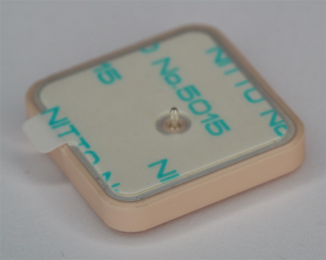
After consulting the module documentation, I settled on a Taoglas antenna (PDF datasheet), which is a 1-inch square device, that needs a 70x70mm ground plane preferably. There were various options; I went with an antenna that is mounted on the reverse side of the board. It is stuck down with double-sided adhesive tape, and then the pin is soldered.
I used a copper-clad board since I had not designed a PCB yet. Ideally it should be double-sided. Mine was single-sided, so I put copper slug tape on the other side, and then patched both sides together with loads of holes and wire links soldered through them all. This part of the exercise was time-consuming and was not fun!
The Lantronix Teseo III module was tricky to patch wires onto. A PCB as mentioned would be far easier.

When powered up, the prototype immediately functioned, which was a surprise, because the board was not close to a window; it was several meters away. I had not expected that, given the construction method. The Teseo III module and the Taoglas antenna seem to function well together, but it would be interesting to try other antennas, and/or a low noise amplifier (LNA) one day.
Anyway, long story short, since the prototype worked, I went ahead and produced a KiCad PCB design, which broadly follows the prototype layout. The boards should arrive in a couple of weeks.

Arduino Connections
The Teseo module cannot work with 5V logic levels, so a 3.3V logic-level Arduino is required. I used an Arduino Uno R4 Minima , adapted for 3.3V operation. If you wish to do the same thing, the information is here: Modifying the Arduino Uno R4: Making it 3.3V-Friendly
The module operates from a 3.3V supply, but the PCB contains a voltage regulator, which needs a 5V supply, which could be taken from from the Arduino board if it has a connection for that (depends on the particular model of Arduino board that is used).
| Module Pin | J1 Pin on PCB | Arduino Pin | Description |
| 2 | 7 | D0/RX | Transmit from GNSS (GPS_TX) |
| 3 | 6 | D1/TX | Transmit from Arduino (GPS_RX) |
| - | 3 | 5V | 5V supply for GNSS board |
| - | 1 | GND | GND |
NMEA Sentences
When powered up, the module should emit a regular stream of text data over the serial UART. The data is known as NMEA sentences; they all begin with $, followed by two characters (often GP, signifying GPS), and then three characters indicating the record type. After that, there is a comma-separated list of parameters, usually ending with an asterisk and a two-digit checksum. Each line (record) in the serial stream has a termination that could be \r\n (i.e. 0x0d 0x0a, which is carriage-return and line-feed respectively).
$GPRMC,004609.000,A,5130.07200,N,00020.76010,W,0.2,0.0,040624,,,A*73
$GPGGA,004609.000,5130.07200,N,00020.76010,W,1,10,0.8,024.48,M,47.1,M,,*76
$GPVTG,0.0,T,,M,0.2,N,0.3,K,A*0C
$GNGSA,A,3,10,23,12,19,17,22,15,24,,,,,1.7,0.8,1.5*29
$GNGSA,A,3,73,71,,,,,,,,,,,1.7,0.8,1.5*24
$GPGSV,3,1,10,24,64,276,29,15,62,176,31,22,44,059,34,13,38,132,*76
In the example above, the first line shows a record called RMC that originated from the GPS system. The record names are cryptic, they are described in the NMEA specification (which is not free, but plenty of online information exists). All I have learned for now, is that the RMC record contains time/date/longitude/latitude information, the GGA record contains altitude, and the GSV record contains satellite information.
You could choose to ignore the checksums from the module, but obviously, if you really are navigating, say a ship, then it wouldn’t be wise to do that!
The checksum is computed as follows:
Set a variable called checksum to zero. Iterate across the NMEA sentence, ignoring the $ and the asterisk, and for each ASCII character, let’s call it c, calculate: checksum = checksum ^ c
Finally, convert the value in checksum into a two-character hexadecimal string, and append it after the asterisk.
Software
There are some pre-existing Arduino libraries, for instance, one called Adafruit_GPS; however, since I was in a learning phase, I wanted to parse the data from scratch so that I could get used to the NMEA sentences that the module would emit. I tested the code using an Arduino Uno R4 Minima board. The code assumes that the Arduino board has a hardware serial interface, known as Serial1. Many Arduino boards have this, but the older Arduino Uno Rev 3 and Arduino Nano (classic version) does not. If you want to use an Arduino Uno Rev 3 or Nano (classic version), then the library code needs to be improved, to be able to use SoftwareSerial capability.
My code isn’t bullet-proof, it will fall over if the data stream is corrupted. The code doesn’t verify checksums either. However, it’s simple-to-use. To use it, add the Teseo Library .ZIP file into the Arduino development environment (IDE) using the menu Sketch->Include Library->Add .ZIP file.
Once that’s done, you can open the example Arduino .ino file by clicking File->Examples->Teseo Library->TeseoTest and run it. The example code demonstrates how to create a GNSS object, and then call flush_data, get_data, and print_data functions.
If it’s successful, you’ll see a stream of information appear repeatedly in the Serial Monitor:

In the screenshot above, the ‘A’ status means the information is valid (‘V’ means it’s not! NMEA peculiarity : )).
The latitude and longitude are indicated in degrees North and East respectively; the example shows a longitude of -0.346 degrees East, which is +0.346 degrees West.
The altitude is interesting; the earth isn’t spherical, it bulges a little, i.e. it is slightly ellipsoidal, plus, on top of that, sea level depends on gravity, and gravity isn’t constant across the earth. Where the earth is denser, it attracts more water, and the mean sea level rises there. There is an internal table of heights inside the module, and the reported altitude takes that table into account, to try to provide an altitude value that is referenced off the internal table of mean sea levels at the reported location. It’s known as an orthometric height. If required, the difference between that and the simpler ellipsoidal model is the value reported as Geoid separation.
The satellite information contains a Source field; A value of 1 indicates a GPS satellite.
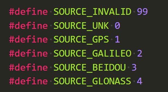
The PRN value is a unique identifier per satellite. The SNR value is between 0 and 99, and the higher the number, the better the signal strength. A value of 0 in the output means that no SNR value was reported by the module (I don’t know what that means other than perhaps that the satellite is not being used for the calculations).
Here’s a breakdown of how to use the code.
First, include the library:
#include <Teseo.h>
Create an object; for instance, call it gnss:
Teseo gnss;
Next, you can initialize it to 9600 baud (this is the default rate that the module uses):
gnss.init(9600);
To read data, two functions are called. The first one clears out the buffer, and the second retrieves fresh data from the device, parses it, and stores it.
gnss.flush_buffer();
gnss.get_data(PRINT_ENABLE);
Use PRINT_ENABLE if you wish to dump the raw NMEA sentences to the Arduino Serial Monitor, otherwise use PRINT_DISABLE.
By now, decoded data is stored inside the gnss object. If you just wish to print that decoded information, use:
gnss.print_data();
If you wish to retrieve specific bits of decoded information, you will have to access the internal structures defined in Teseo.h, since the library is still very basic!
For instance, to obtain the current hours and minutes:
hour = gnss.rmc.hour;
min = gnss.rmc.min;
Summary
This blog post examined how satellite navigation systems worked, and a project was developed to make use of a GNSS Teseo III module from ST / Lantronix with the Arduino.
A simple Arduino library was created (to see how to create a custom library, click here: Arduino Library Creation and Testing Workflow ), that decodes the stream of NMEA sentences arriving from the module, to obtain time, location, altitude and satellite information.
Based on the functioning prototype, a PCB design was created, and although that has not been tested so far, hopefully, it will soon.
Thanks for reading!
References
Lantronix PNT Series Specifications and Resources
ST Teseo Software User Manual (PDF)
Taoglas CGGBP.24.4.A.02 Antenna Datasheet (PDF)
Top Comments