Table of contents
Abstract
Ever had a need to install RTC module already configured for the correct time? Or have you wondered how precise is given real time clock but didn't have time to build dedicated circuit to test it? Well - then maybe this project can be useful for you
Project
Intro
This project began as a byproduct of the roadtest I was preparing, when I planned to add external Real Time Clock module to the Raspeberry Pi Pico. Given the fact that it was lacking Internet connection, some method of setting correct time needed to be arranged. Not wanting to write some interactive, UART accessible, time setting dialog and taking advantage of the fact that most of RTC modules have battery backup integrated - so they can be moved between systems without losing information about current time (or even stopping the clock), I have built simple programmer, which - after retrieving correct time from NTP (Network Time Protocol) server, is writing it into RTC module, which could be then moved to the target system.
Construction
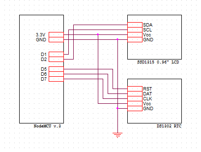
RTC module programmer is built using (ESP8266 based) NodeMCU board, which has WiFi interface builtin - so it can easily obtain information about current time from some reference NTP server from the Internet. Initially, it only consisted of NodeMCU board and DS1302 RTC module to be programmed, but after learning of poor clock stability of the module I own, an LCD display was added, allowing easy monitoring of clock's time drift. Final construction has a schematics as below:

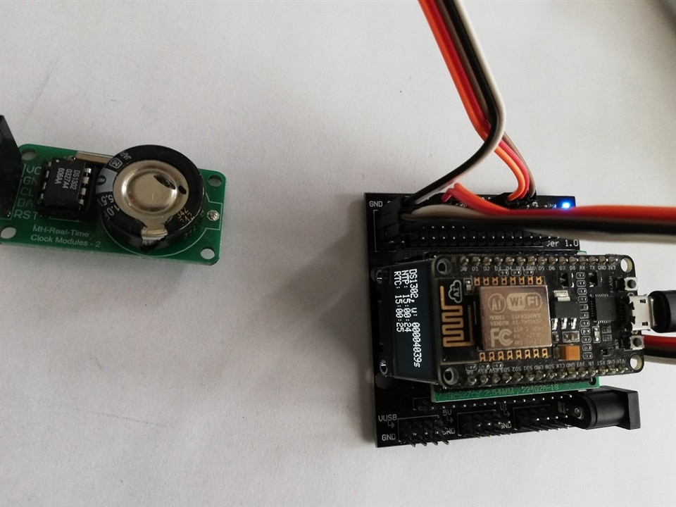
and looks like this

LCD module (with the resolution 128x32, allowing for display of four lines of text) is wedged between NodeMCU and baseboard and secured using hot melt glue - this way it stays in the place during programmer operation.
RTC module is on purpose connected using cables - the connection is by design temporary and should be easily disconnected. RTC is a typical low-cost DS1302 module, slightly modified by replacing the CR2032 battery socket with the 1F supercapacitor (DS1302 has a circuit to provide charging current to the back-up capacitor/battery).
The principle of operation is as below:
- after boot-up, module is connecting to the WiFi and obtaining time from one of NTP servers from pool.ntp.org server pool (operators of this pool are employing DNS based load distribution, when every DNS query is obtaining differently sorted list of servers - thus contacting the first one from the list distributes client requests between pool servers),
- after correct time is obtained, it is written to the DS1302 module,
- then, in the main loop, every second NTP update attempt is made (library limits this to one call every minute by default to not overload the servers, so most of the attempts are unsuccessful but this is not a problem),
- after this, three values are displayed on the LCD
- time from boot (in seconds)
- time from NTP server (reference time)
- time from RTC module
This way RTC module operation can be monitored - in the video below, one can see that after about 16h of operation (58600s), RTC time is about 8s fast.
A source code - in form of Aruino IDE sketch and of somewhat prototype quality - is included below.
Summary
This project shows again how using Arduino IDE and an ecosystem of libraries and board support packages, one can build an usable project in the less time than writing and documenting this Project14 entry. Additionally, one is not forced to install and learn new toolset each time he wants to switch to different CPU architecture/board type (as long as there is Arduino support provided) which is huge boon when quickly evaluating new hardware.
References
Power Integrations Reference Design Kit RoadTest
DS1302 module supercap modification

![[DS1302] RTC module programmer/tester](https://community-storage.element14.com/communityserver-components-secureimagefileviewer/articles/a86c87daa3034e77a8c753efd349d09c/a/4efc5a66059b43338ad1d1ca673b3b22/5100.project_img.jpg-300x300x2.jpg?sv=2016-05-31&sr=b&sig=WxqS01Co9zanI%2B%2F4%2BPRqGxbUpTn35YPkRuq5z3adb04%3D&se=2026-02-14T23%3A59%3A59Z&sp=r&_=ipTFq22Fij1qGrqCvKs5Hw==)
Top Comments