element14 Community
element14 Community
    Register Log In
  • Site
  • Search
  • Log In Register
  • Community Hub
    Community Hub
    • What's New on element14
    • Feedback and Support
    • Benefits of Membership
    • Personal Blogs
    • Members Area
    • Achievement Levels
  • Learn
    Learn
    • Ask an Expert
    • eBooks
    • element14 presents
    • Learning Center
    • Tech Spotlight
    • STEM Academy
    • Webinars, Training and Events
    • Learning Groups
  • Technologies
    Technologies
    • 3D Printing
    • FPGA
    • Industrial Automation
    • Internet of Things
    • Power & Energy
    • Sensors
    • Technology Groups
  • Challenges & Projects
    Challenges & Projects
    • Design Challenges
    • element14 presents Projects
    • Project14
    • Arduino Projects
    • Raspberry Pi Projects
    • Project Groups
  • Products
    Products
    • Arduino
    • Avnet Boards Community
    • Dev Tools
    • Manufacturers
    • Multicomp Pro
    • Product Groups
    • Raspberry Pi
    • RoadTests & Reviews
  • Store
    Store
    • Visit Your Store
    • Choose another store...
      • Europe
      •  Austria (German)
      •  Belgium (Dutch, French)
      •  Bulgaria (Bulgarian)
      •  Czech Republic (Czech)
      •  Denmark (Danish)
      •  Estonia (Estonian)
      •  Finland (Finnish)
      •  France (French)
      •  Germany (German)
      •  Hungary (Hungarian)
      •  Ireland
      •  Israel
      •  Italy (Italian)
      •  Latvia (Latvian)
      •  
      •  Lithuania (Lithuanian)
      •  Netherlands (Dutch)
      •  Norway (Norwegian)
      •  Poland (Polish)
      •  Portugal (Portuguese)
      •  Romania (Romanian)
      •  Russia (Russian)
      •  Slovakia (Slovak)
      •  Slovenia (Slovenian)
      •  Spain (Spanish)
      •  Sweden (Swedish)
      •  Switzerland(German, French)
      •  Turkey (Turkish)
      •  United Kingdom
      • Asia Pacific
      •  Australia
      •  China
      •  Hong Kong
      •  India
      •  Korea (Korean)
      •  Malaysia
      •  New Zealand
      •  Philippines
      •  Singapore
      •  Taiwan
      •  Thailand (Thai)
      • Americas
      •  Brazil (Portuguese)
      •  Canada
      •  Mexico (Spanish)
      •  United States
      Can't find the country/region you're looking for? Visit our export site or find a local distributor.
  • Translate
  • Profile
  • Settings
Learning Center
  • Learn
  • More
Learning Center
Blog Experimenting with Op Amps: Schmitt-trigger
  • Blog
  • Documents
  • Polls
  • Members
  • Mentions
  • Sub-Groups
  • Tags
  • More
  • Cancel
  • New
Join Learning Center to participate - click to join for free!
  • Share
  • More
  • Cancel
Group Actions
  • Group RSS
  • More
  • Cancel
Engagement
  • Author Author: Jan Cumps
  • Date Created: 18 May 2023 7:55 PM Date Created
  • Views 7802 views
  • Likes 20 likes
  • Comments 31 comments
  • opamp
  • analogue
  • analog
Related
Recommended

Experimenting with Op Amps: Schmitt-trigger

Jan Cumps
Jan Cumps
18 May 2023

The Art Of Electronics features a set of practical op-amp circuits. One of them is an op-amp controlled Schmitt-trigger. In this post, I build the circuit and show some lab techniques. 

image
image source: edited photo of page 267 of my copy of The Art Of Electronics, 3rd edition

A Schmitt-trigger is a circuit that will clean up a noisy digital input signal. In the ideal world, digital signals are low or high. In the real world, there can be noise on those signals. When you switch between levels, that noise may cause glitches in the output, if the signal crosses the logic level a few times while switching - due to the noise:

image
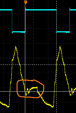
image source: my capture of the actual circuit

The purpose of the Schmitt-trigger is to take the first logic level crossing, and ignore the noise. It builds a safety zone (hysteresis) that takes care that noise will not generate bounce in the output.

This post tries to address two topics: 

  • build and analysis of the circuit
  • how you can test it

The circuit is simple:

  • the non-inverting input of the op-amp is set to a reference point (the logic level), defined by a resistor divider. In this case: Vref / 2 = 2.5 V
  • the input that needs to be cleaned up goes to inverting input
  • assuming a gain of 1: when the inverting is above the non-inverting, the output wants to go negative. When the inverting input is below the non-inverting, the output wants to go positive

If the input hovers around that switching point when changing levels - because the input signal is noisy - the output would glitch.at each crossing. during the level switch

image

What we want, is that the output immediately reacts at the first crossing, then keeps its value until the input is switching again. We can achieve that with positive feedback. Positive feedback boosts the gain and will exaggerate the effect of the first level crossing. Instead of nicely following the input, it will flop to the right power rail. Then that feedback will help to keep the op-amp in that state- overruling the noise. The op-amp will only flip back if the input has switched enough to overcome that feedback hold. It splits the logic level into two logic levels: one high voltage level, and one low level. The op-amp will only flip output if the input has moved from above the high level until under the low level, or the other way around. That's hysteresis. That's a Schmitt-trigger.

These levels can be calculated. The high level is defined by the voltage set on the non-inverting input. The low level is a function  of the positive feedback (R7 and R6 || R5). (read comment  (Missing Forum Reply)  and follow ups)

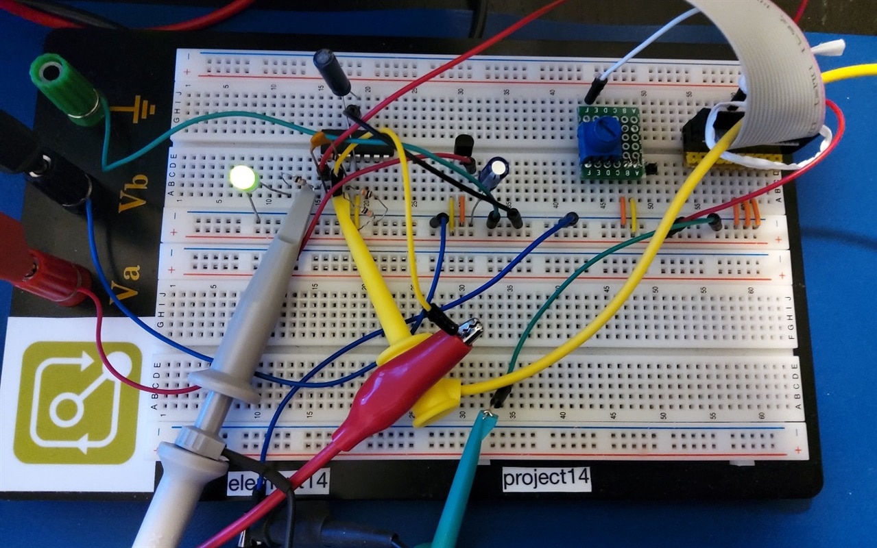
Building the circuit

Although a comparator is better suited for this, I used an op-amp. In this case, one that can be driven to ground rail: LM324N. It's not necessary to have a rail-to-rail or to-ground op-amp. A simpler one may meet your requirements. As voltage reference, I used an 7805.

image

For first tests, I used a potentiometer to control the input, and an LED to see what happened on the output

image

First measurements with a multimeter

I probed the input voltage with a voltmeter and used the potentiometer to move that input value between 0 and 5 V. Then I looked if the LED switched on or off. This learned me that the logic levels are 1.9 V and 2.8 V. I also looked at the switching behaviour of the output, with a handheld oscilloscope:

image image

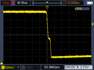
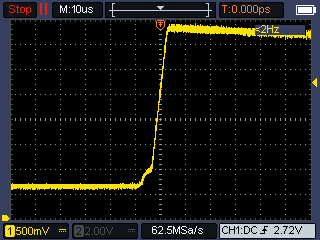
This is good. My potentiometer movements were slow, but the output switches fast. The speed may be improved by putting a small capacitor in parallel with the feedback resistor (10 - 100 pF).

Test the level crossover with an arbitrary waveform generator

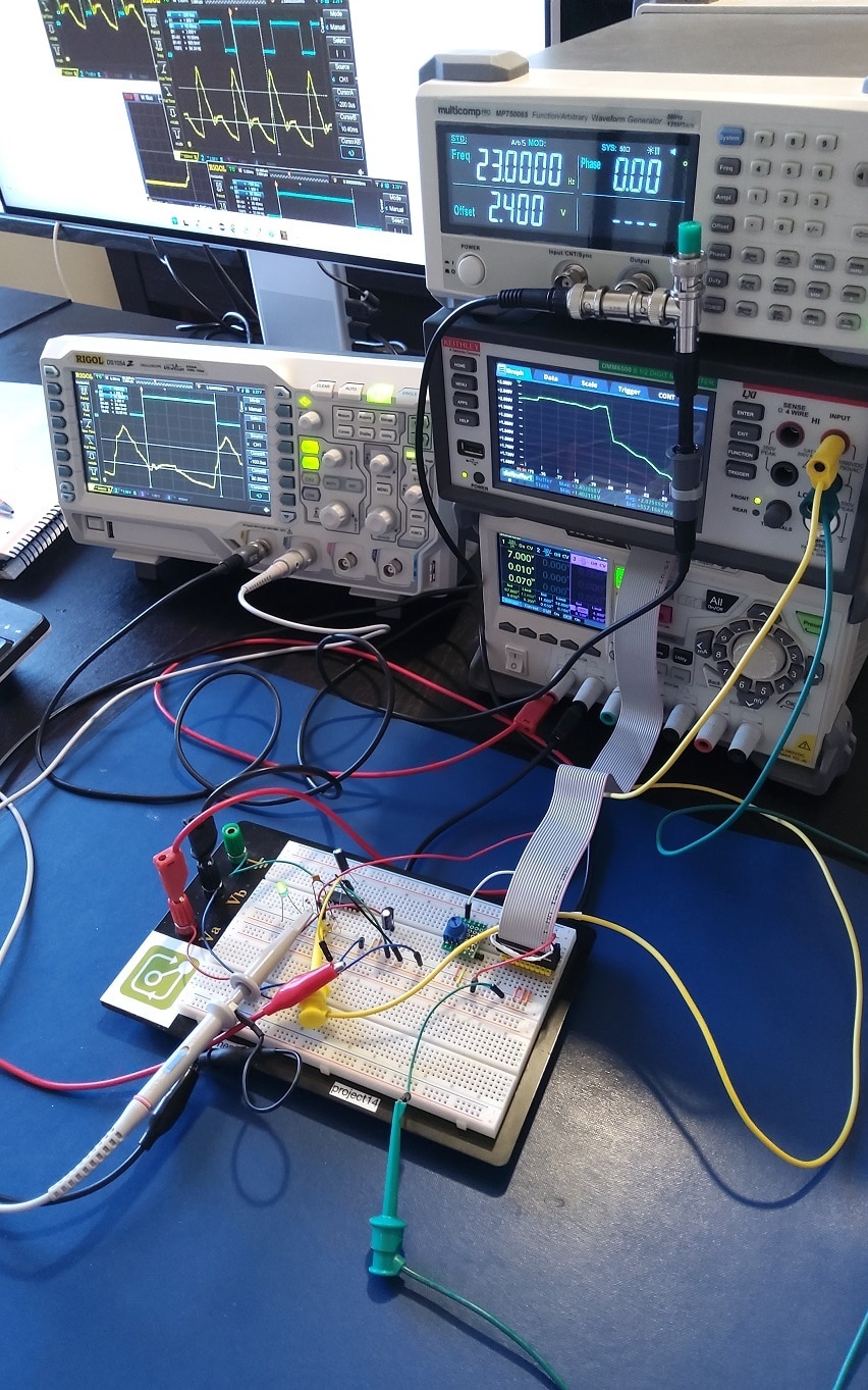
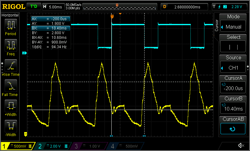
The first test shows that the trigger switches fast when the expected levels are crossed. But it's not an easy way to prove that the hysteresis deals with multiple level crossings. An arbitrary waveform generator can help to create multiple crossings. I used an affordable Multicomp Pro MP750065 to generate such a form:

image

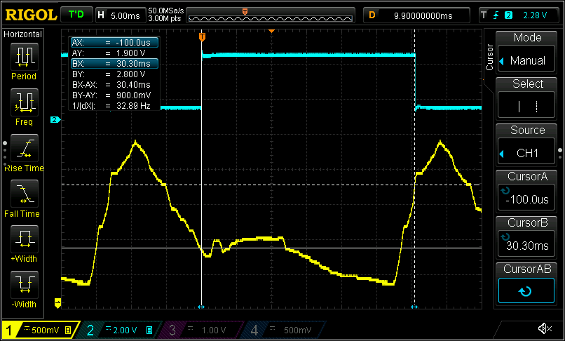
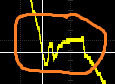
On this image, you see that at the low level, the threshold is crossed several times, but the design nicely ignores it. It will only entertain low level switches once the signal has crossed the high level:

image

That's it. If you look at the breadboard photo, you may spot a flat cable. That's because I'm preparing another post where I try to automate the measurements, using a DMM6500 and a 10 channel multiplex card. But that 'll be posted in the  Test & Tools  area …

image

  • Sign in to reply
  • jc2048
    jc2048 over 2 years ago in reply to Jan Cumps

    "...why can  jc2048 simplify the non-inverting circuit..."

    'Why' (as in the theoretical basis for it) I'll leave to someone who is more academic than me. Thévenin works for impedances, so the (linear) network that you're analysing can include capacitors and inductors, as well as resistors. You'd really want the Laplace transform as a foundation before starting on it.

    The 'how' in this case is quite easy and worth knowing, as the situation with a potential divider crops up quite a lot with biasing in analogue circuits. (Hope I get this right. Someone correct me if any of it is wrong.)

    There are three steps.

    One, identify the network. Here it's very simple. A voltage source (5V) across two resistors, R6 and R5, with the single output port being between the node between the two resistors and the circuit reference (ground).

    Two, determine the voltage of the source in the equivalent circuit. That will be the same as the unloaded output of the network. Here, because it's a potential divider with equal value resistors, it will be half of 5V, which is 2.5V.

    Three, imagine you've opened all current sources (here there aren't any) and shorted all voltage sources (+5V is connected to ground) and calculate the resulting impedance seen from the output port to the reference point (ground). In this case, with two equal resistors, that will be 10k in parallel with 10k which is 5k.

    So it's fairly trivial to do, so much so in this case that it was just a matter of writing the values on the drawing.

    Where it helps me with understanding the circuit operation is if you consider the 5k and the 10k resistors in my reworked circuit as being like a rigid lever with the pivot point being the top of the voltage source. Because the op amp doesn't take any current, the currents through the two resistors are always the same, so the voltage drop across the 10k will be twice the voltage drop across the 5k (assuming the output of the op amp stays in the region where it operates normally, of course). Put another way, as the op amp output voltage moves around the 2.5V, the voltage at the non-inverting input moves by a third of that. So we come to a quick understanding of the way the thresholds relate to the output voltage, without even touching a calculator.

    • Cancel
    • Vote Up 0 Vote Down
    • Sign in to reply
    • More
    • Cancel
  • Jan Cumps
    Jan Cumps over 2 years ago in reply to phoenixcomm

    both. I like to play with electronics and I like to "community"

    • Cancel
    • Vote Up 0 Vote Down
    • Sign in to reply
    • More
    • Cancel
  • phoenixcomm
    phoenixcomm over 2 years ago in reply to Jan Cumps

    (tongue and cheek) Then this is an excuse for the blog, or do just like to write like i do.

    I am really envious of the clean space on your bench... even on my desk where I write software only has room for my keyboard, marble mouse, and my Mike.

    You don't have permission to edit metadata of this video.
    Edit media
    x
    image
    Upload Preview
    image

    ops forgot about my Tardis USB hub, which makes noises and has a little blue light on top and it blinks. ,  

    • Cancel
    • Vote Up 0 Vote Down
    • Sign in to reply
    • More
    • Cancel
  • Jan Cumps
    Jan Cumps over 2 years ago in reply to jc2048
    [quote userid="36226" url="~/learn/learning-center/f/forum/52955/experimenting-with-op-amps-schmitt-trigger/209463"]Be aware that, depending on the JFET you choose, the thresholds may well be below ground. Might be useful with a fairly large signal around earth (ac coupled, with a load resistor to 0V), but you might be puzzled as to why it's not doing anything if you feed it a signal between the rails.[/quote]

    Simulating with a jfet (switch type) and bjt (not a high gain one) I have here:

    image

    jfet schmitt trigger.zip

    • Cancel
    • Vote Up 0 Vote Down
    • Sign in to reply
    • More
    • Cancel
  • scottiebabe
    scottiebabe over 2 years ago in reply to Jan Cumps

    Or...

    image

    • Cancel
    • Vote Up 0 Vote Down
    • Sign in to reply
    • More
    • Cancel
>
element14 Community

element14 is the first online community specifically for engineers. Connect with your peers and get expert answers to your questions.

  • Members
  • Learn
  • Technologies
  • Challenges & Projects
  • Products
  • Store
  • About Us
  • Feedback & Support
  • FAQs
  • Terms of Use
  • Privacy Policy
  • Legal and Copyright Notices
  • Sitemap
  • Cookies

An Avnet Company © 2025 Premier Farnell Limited. All Rights Reserved.

Premier Farnell Ltd, registered in England and Wales (no 00876412), registered office: Farnell House, Forge Lane, Leeds LS12 2NE.

ICP 备案号 10220084.

Follow element14

  • X
  • Facebook
  • linkedin
  • YouTube