The Art Of Electronics features a set of practical op-amp circuits. One of them is an op-amp controlled Schmitt-trigger. In this post, I build the circuit and show some lab techniques.

image source: edited photo of page 267 of my copy of The Art Of Electronics, 3rd edition
A Schmitt-trigger is a circuit that will clean up a noisy digital input signal. In the ideal world, digital signals are low or high. In the real world, there can be noise on those signals. When you switch between levels, that noise may cause glitches in the output, if the signal crosses the logic level a few times while switching - due to the noise:
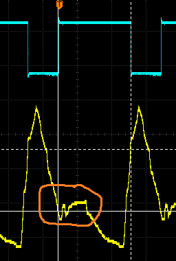
image source: my capture of the actual circuit
The purpose of the Schmitt-trigger is to take the first logic level crossing, and ignore the noise. It builds a safety zone (hysteresis) that takes care that noise will not generate bounce in the output.
|
This post tries to address two topics:
|
The circuit is simple:
- the non-inverting input of the op-amp is set to a reference point (the logic level), defined by a resistor divider. In this case: Vref / 2 = 2.5 V
- the input that needs to be cleaned up goes to inverting input
- assuming a gain of 1: when the inverting is above the non-inverting, the output wants to go negative. When the inverting input is below the non-inverting, the output wants to go positive
If the input hovers around that switching point when changing levels - because the input signal is noisy - the output would glitch.at each crossing. during the level switch

What we want, is that the output immediately reacts at the first crossing, then keeps its value until the input is switching again. We can achieve that with positive feedback. Positive feedback boosts the gain and will exaggerate the effect of the first level crossing. Instead of nicely following the input, it will flop to the right power rail. Then that feedback will help to keep the op-amp in that state- overruling the noise. The op-amp will only flip back if the input has switched enough to overcome that feedback hold. It splits the logic level into two logic levels: one high voltage level, and one low level. The op-amp will only flip output if the input has moved from above the high level until under the low level, or the other way around. That's hysteresis. That's a Schmitt-trigger.
These levels can be calculated. The high level is defined by the voltage set on the non-inverting input. The low level is a function of the positive feedback (R7 and R6 || R5). (read comment (Missing Forum Reply) and follow ups)
Building the circuit
Although a comparator is better suited for this, I used an op-amp. In this case, one that can be driven to ground rail: LM324N. It's not necessary to have a rail-to-rail or to-ground op-amp. A simpler one may meet your requirements. As voltage reference, I used an 7805.

For first tests, I used a potentiometer to control the input, and an LED to see what happened on the output
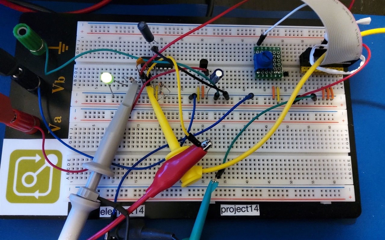
First measurements with a multimeter
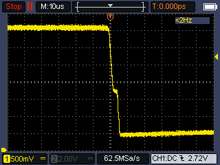
I probed the input voltage with a voltmeter and used the potentiometer to move that input value between 0 and 5 V. Then I looked if the LED switched on or off. This learned me that the logic levels are 1.9 V and 2.8 V. I also looked at the switching behaviour of the output, with a handheld oscilloscope:
 |
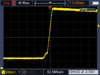 |
This is good. My potentiometer movements were slow, but the output switches fast. The speed may be improved by putting a small capacitor in parallel with the feedback resistor (10 - 100 pF).
Test the level crossover with an arbitrary waveform generator
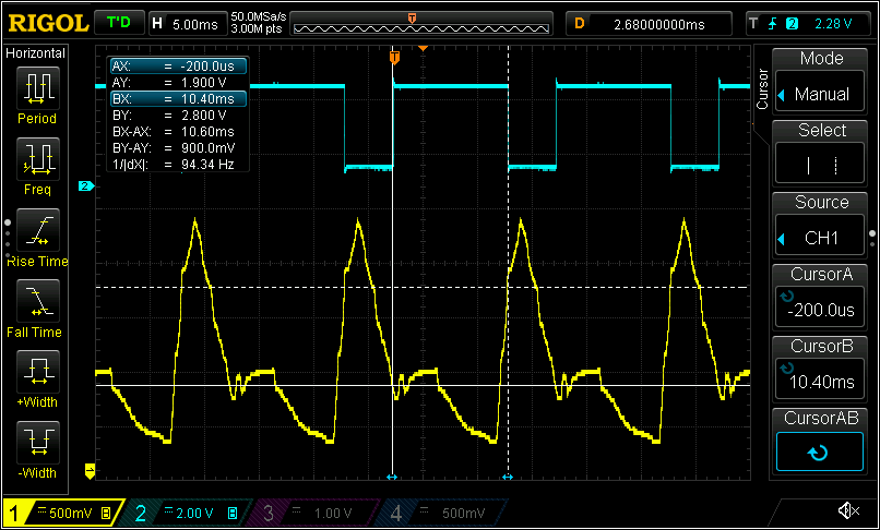
The first test shows that the trigger switches fast when the expected levels are crossed. But it's not an easy way to prove that the hysteresis deals with multiple level crossings. An arbitrary waveform generator can help to create multiple crossings. I used an affordable Multicomp Pro MP750065 to generate such a form:
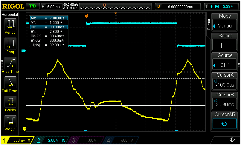
On this image, you see that at the low level, the threshold is crossed several times, but the design nicely ignores it. It will only entertain low level switches once the signal has crossed the high level:
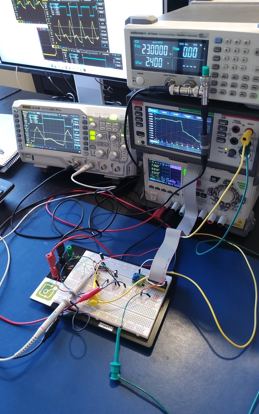
That's it. If you look at the breadboard photo, you may spot a flat cable. That's because I'm preparing another post where I try to automate the measurements, using a DMM6500 and a 10 channel multiplex card. But that 'll be posted in the Test & Tools area …

-

DAB
-
Cancel
-
Vote Up
0
Vote Down
-
-
Sign in to reply
-
More
-
Cancel
-

Jan Cumps
in reply to DAB
-
Cancel
-
Vote Up
0
Vote Down
-
-
Sign in to reply
-
More
-
Cancel
-

jc2048
in reply to Jan Cumps
-
Cancel
-
Vote Up
0
Vote Down
-
-
Sign in to reply
-
More
-
Cancel
-

Jan Cumps
in reply to jc2048
-
Cancel
-
Vote Up
0
Vote Down
-
-
Sign in to reply
-
More
-
Cancel
Comment-

Jan Cumps
in reply to jc2048
-
Cancel
-
Vote Up
0
Vote Down
-
-
Sign in to reply
-
More
-
Cancel
Children