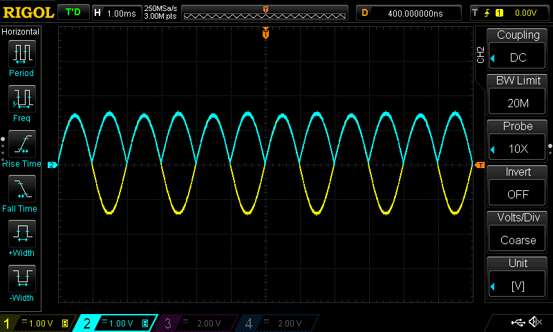
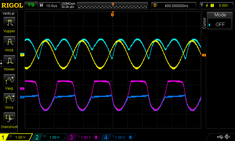
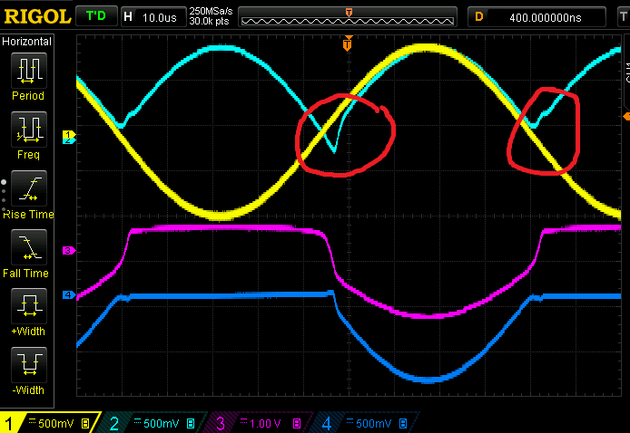
The Art Of Electronics features a set of practical op-amp circuits. They have several full-wave rectifiers. I'm trying the simplest one. You don't need fancy devices. A pair of 741s will do.
The circuit:

image source: my copy of the book. fair use.
Looking at the node where the arrow points to:
- for positive values, the first op-amp is an inverting buffer.
- for negative values, the op-amp output has a 0.6V dc bias, the right side of the feedback resistor will be at 0 V (ground).
hint: the 0.6 V output is generated by the op-amp to drive the inverting input to the same value as the + input (ground), effectively clamping the output to 1 diode drop above ground.
Looking at the second op-amp:
- it is an op-amp with a summing node. Two signals at the inverting input are summed and inverted. The amplification factor is defined by the input resistor and the feedback resistor.
- for the input signal, the amplification = -1 * R/R = -1 (the input resistance equals the feedback resistance, resulting in the -1 amplification factor, doubling and inverting the signal)
- for the signal coming from op-amp 1, the amplification = -1 * R / (R/2) = -2 (the input resistance is half the feedback resistance, resulting in the -2 amplification factor)
- it is an inverting amplifier for the input. Both positive and negative signals are amplified by -1.
- for the signal coming from the first op-amp, it acts as a -2 amplifier.
- for positive inputs, this results in Vin * -1 + Vin * -1 * -2 = -Vin + 2Vin = Vin -> result: Vin, positive Vin comes out as positive Vin (see comment)
- for negative inputs, this results in Vin * -1 (making Vin positive) + Vin * 0 * -1 -> result -Vin: negative Vin comes out as positive Vin
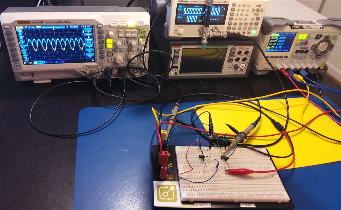
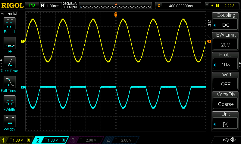
Here is the result: The blue line is the output. Underneath it, you see the input. The output overlaps the input for the positive part. It inverses the negative part. No diode drop.
