
In a sense, electricity drives the world’s economy. With climate change becoming a major concern, many nations have committed to decarbonizing their economies, replacing fossil fuels with renewable energy sources such as wind energy. Wind energy is one of the most efficient means of safe and environmentally sustainable energy production. It is local, zero emissions, competitive, and inexhaustible. Wind turbines are typically constructed in remote locations where supplying electricity through standard power lines is difficult. Wind power offers several benefits to these areas, such as job creation and increased income for the landowners. This learning module covers the fundamentals of energy generation through wind turbines, their components, and some essential applications.
Related Components | Test Your Knowledge 
2. Objectives
Upon completion of this module, you will be able to:
- Understand the operation of wind turbines
- Describe the different components of a wind power system
- Discuss the design considerations for wind power
- Create your own micro-wind turbine
3. Basic Concepts
Wind is caused by the movement of air from areas of high pressure to areas of low pressure. It is a natural response to imbalances in atmospheric pressure. Factors that contribute to the creation of wind include:
- Differential Heating: The sun's energy heats the earth's surface unevenly. Different surfaces, such as land, water, and vegetation, absorb and retain heat at different rates. This uneven heating leads to variations in temperature across the earth's surface.
- Pressure Gradient: The uneven heating of the earth's surface creates regions of different air pressure. Warm air tends to rise, creating an area of low pressure, while cooler air sinks, creating an area of high pressure. The pressure gradient between these regions sets up the driving force for the movement of air.
- Coriolis Effect: As the earth rotates on its axis, a phenomenon known as the Coriolis effect comes into play. The Coriolis effect deflects the path of moving objects, including air. In the Northern Hemisphere, the deflection is to the right, and in the Southern Hemisphere, to the left. This deflection is caused by the rotation of the earth and influences the direction of wind flow.
- Friction: Friction between the moving air and the earth's surface affects the speed and direction of wind. Near the surface, friction slows down the wind speed and causes a deviation from the geostrophic wind (the theoretical wind that would exist without the influence of friction).
Combining these factors, air moves from areas of higher pressure to areas of lower pressure, following a curved path due to the Coriolis effect. The resulting movement of air is what we perceive as wind. The speed and direction of wind are influenced by the interaction of these factors, as well as other local conditions such as topography, vegetation, and temperature gradients.
Wind patterns can also be influenced by large-scale atmospheric phenomena such as jet streams, monsoons, and local weather systems. These factors further contribute to the complex nature of wind patterns. Windmills or wind turbines are then able to harness this motion to create electricity.
3.1 How a Wind Turbine Works
A wind turbine produces electrical energy from wind energy by using the force from the rotor blades. The flow across the wind turbine blade decreases air pressure on only one side of the blade. The variation in pressure between the two sides of the blades creates lift and drag forces. Because the lift force is greater than the drag force, the rotor spins. The rotor can connect directly to the generator or through a shaft and a gearbox. This translation of aerodynamic force to the rotation of a generator creates electricity.
3.2 The Key Components of a Wind Turbine
Figure 1 depicts a rotor, nacelle, and tower, the three essential components of a wind turbine.
The rotor consists of three blades and a hub (the mechanical link between the blades and the low-speed shaft). The turbine blades capture the wind’s kinetic energy and convert it into mechanical motion. A rotational shaft transmits this motion to the gearbox. A yawing mechanism enables the turbine to rotate on its vertical axis in order to orient the rotor in the wind direction and maximize the captured energy. The nacelle houses a gearbox and generator. Two shafts, low-speed and high-speed, constitute the turbine drivetrain. The low-speed shaft connects the rotor to the gearbox, while the high-speed shaft connects the gearbox to the generator. The gearbox plays an important function: producing a high-speed, low-torque rotational force from the low-speed torque produced by the rotation of the blades. The gears transmit this high-speed, low-torque rotational force to the generator, and a transformer steps up the generator voltage for transmission.

Figure 1: Key Components of a Wind Turbine. Image Source: U.S. Department of Energy
3.3 How Much Power Does a Wind Turbine Produce?
The power generated by a wind turbine depends on two factors:
- Design of the turbine
- Properties of the wind resource
A modern wind turbine is designed to work with wind speeds from 30 to 55 mph, producing power at its rated or full capacity. At slower wind speeds, production drops considerably. If wind speed is reduced by 50%, the power generated is decreased by a factor of eight. Wind turbines, on average, do not generate near their full capacity due to inconsistent wind or internal power conversion inefficiencies.
3.4 Maximum Efficiency of a Wind Turbine
The maximum power possible to be produced by a wind turbine, irrespective of its design, is given by Betz's Law. Betz's Law states that no turbine can capture more than 16/27 (59.3%) of the wind's kinetic energy. The value of 16/27 (59.3%) is known as Betz's limit.
The following equation gives the theoretical wind power per given swept area by a wind turbine: P = 0.5 x ρ x A x v3 x Cp
Where: P is power in watts, ρ (rho) is air density in Kg/m3, A is the circular area swept by the rotor blades in m2, v is the wind velocity in m/s, and Cp is the power coefficient (efficiency), which the wind turbine generates from the total energy present in the wind at a specific wind speed.
3.5 The Advantages and Disadvantages of Wind Energy
The key advantages and disadvantages of a wind turbine are as follows:
| Advantages | Disadvantages |
|---|---|
| Comparatively cheaper than other fuel sources | Unreliable because wind is unpredictable |
| Wind is inexhaustible | Ice and rime formation on turbine blades in cold climates can result in turbine failure. |
| Does not pollute the air or water | Wind turbines produce noise and alter visual aesthetics. |
| Creates employment in design, manufacturing, installation, and maintenance | Can impact local wildlife; birds and bats can potentially run into spinning turbine blades |
| The land below each turbine can still be used for animal grazing or farming | Requires large open areas for setting up wind farms |
3.6 Wind Energy Storage
Wind energy is an intermittent power source. The speed of wind varies on an hourly, monthly, and seasonal basis, causing high variance in the output of wind turbines. A wind turbine pauses its operation during very high and low wind speeds. Because of this unpredictability, a wind turbine must store energy to consistently meet the demands of its end customers. Energy can be stored in a turbine by using the following methods:
- Chemical Storage: Power can be stored in batteries as chemical energy. The stored chemical energy is converted into electricity to serve the varying load demand.
- Hydrogen Fuel Cells: The power generated from the wind turbine can run a hydrogen generator that electrolyzes water. A fuel cell power system then converts this stored hydrogen to electricity.
- Compressed Air Storage: The excess power generated by the wind turbine during off-peak hours can drive a compressor to pre-compress the air and store it in large storage reservoirs. The compressed air can be used by traditional gas turbines to produce electricity.
- Pumped-hydroelectric energy storage: Hydroelectric plants store energy using two interconnected reservoirs. One reservoir is situated at a higher elevation than the other. The upper reservoir is pumped with water during times of surplus energy. Conversely, the upper reservoir releases water during excess demand. The flow of the water generates electricity as it passes the turbines towards the lower reservoir.
- Supercapacitor energy storage: Supercapacitors smooth the system's output power by storing energy and discharging it when wind speed changes. This helps resolve high current fluctuations, resulting in a more efficient grid system. Supercapacitors are needed especially during strong winds.
4. Analysis
Wind Energy Conversion System
Figure 2 depicts a wind energy conversion system that includes a wind turbine, generator, interconnection apparatus, control systems, and power electronics converters. A wind turbine can be designed for a constant or variable speed operation. Variable-speed wind turbines can produce 8% to 15% more energy output than their constant-speed counterparts. However, electronic power converters are needed to provide their loads with a fixed frequency and voltage. Most wind turbines are equipped with reduction gears between the low-speed turbine rotor and the high-speed three-phase generators. Direct drive configurations are also available, where a generator is coupled to a wind turbine's rotor directly, offering high reliability, low maintenance, and lower cost for certain turbines.
Wind energy conversion systems currently use permanent magnet synchronous generators and induction generators, including squirrel cage and wound rotor types. For small to medium-power wind turbines, permanent magnet and squirrel cage induction generators are often used because of their reliability and cost advantages. High-power wind turbines typically use induction, permanent magnet, and wound field synchronous generators. Wind turbines use power electronics converters, such as forced-commutated PWM (pulse width modulation) inverters, to provide high power quality, fixed voltage, and fixed frequency output.
Some high-power wind turbines use double PWM converters for effective power control. This provides a bi-directional power flow between the turbine generator and the utility grid.

Figure 2: Wind Energy Conversion System
Design Considerations for Wind Power
Standard wind turbine design involves the conceptual assembling of many mechanical and electrical components into a machine that can convert the wind's fluctuating power into a functional form. This process must manage several limitations:
- Rotor Axis Orientation: The orientation of the rotor axis is of prime importance in wind turbine design. Wind turbines consist of two types: horizontal and vertical. In horizontal-axis turbines, the rotor's axis is parallel to the ground. In contrast, in vertical-axis turbines, the axis of the rotor and the ground is perpendicular to each other. Horizontal axis turbines are usually propeller-type, while vertical axis turbines have C-shaped blades. Horizontal axis turbines capture more wind, typically resulting in a higher power output when compared with vertical turbines. The vertical axis turbines are easy to design and maintain but offer lower performance than the horizontal axis turbine types due to the high drag of their simple rotor blade design.
- Rotor Position: The design of turbines can be such that either the rotor's front side (upwind) or rear side (downwind) faces the wind. Most commercial turbines use an upwind design. The significant advantage of upwind turbines is that there are no wake losses (reductions in power output due to the presence of another wind turbine). The primary benefit of downwind machines is that the blades can be made from cheaper and more flexible materials.
- Design Tip Speed Ratio: Tip speed ratio (TSR) is the ratio between the actual wind speed and the speed of the blade's tips. A rotor's design tip speed ratio is the tip speed ratio where the power coefficient is at its maximum. A high design tip speed ratio rotor will have less blade area than the rotor of a slower machine of the same diameter.
- Pitching of blades: In low to medium wind velocity, the blades of the turbine are pitched at the optimum angle, in order to obtain the maximum co-efficient of power and thus, the maximum amount of energy. A pitch system comprises a pitch sensor, a microcontroller, and a pitch actuator.

Figure 3: Design of a wind turbine’s blade
- Blade length: The design of a wind turbine’s blades is critical. Wind turbine blades are designed with an aerodynamic shape called airfoils. The structure of the rotor blades must extract maximum energy from the wind while being strong enough to stand steady, periodic, and randomly changing loads. An optimum rotor blade design is necessary for maximum power extraction.
- Tower Structure: The rotor nacelle assembly of a wind turbine is placed at a considerable height so that the rotating blade tips do not touch the ground. A taller tower is essential as winds are nearly always stronger and less turbulent with greater height. The tower height should be as high as possible from a power extraction standpoint. The choice of tower height is an economic trade-off of increased energy capture versus increased cost.
Wind Turbine Controls
Wind turbine control systems ensure a wind turbine's reliable and safe operation. The main control systems in a modern wind turbine are as follows:
- Pitch control: The pitch control system continually regulates the wind turbine's blade pitch angle to enhance wind energy conversion efficiency and power generation stability. It also secures the turbine in case of high wind speeds or emergencies. Pitch is the angle the airfoil chord makes with the rotor plane of rotation. With variable pitch designs, bearings are inserted between the blades and rotor hub. When the wind speed becomes too great, rotor blades are turned along their longitudinal axis to allow some wind to pass by without increasing lift. At low wind speeds, blades are turned into the wind. The advantage of a pitch-controlled method is that relatively constant rotor speeds can be maintained within an extensive range of wind speeds.
- Yaw control: Yaw is the adjustment of the entire wind turbine’s orientation. An active yaw control system must orient the horizontal-axis wind turbine with the rotor against the wind to maximize the wind power output. A large wheel called a yaw bearing turns the nacelle with the rotor into the wind. At very high speeds, the rotor is intentionally turned away from the direction of the trailing wind, reducing the total volume of air passing through the rotor and the power. Turbines running with yaw or tilt control may experience large fatigue loads because yawing bends the rotor.
- Stall Control: The stall control regulates the power of a wind turbine by stalling the blades after the rated speed is achieved. In stall-controlled wind turbines, blades are shaped such that excess wind speed creates sufficient turbulence on the backside and the rotor stalls. The primary advantage of stall control is that the rotors remain fixed to the hub, which removes many complex control mechanisms necessary in pitch and yaw control methods.
- Brake Torque Control: Using a brake system is necessary to park a wind turbine and stop a stall-regulated wind turbine. Such a brake system is attached to either the high-speed or low-speed shaft. Brakes are typically applied through pneumatic, hydraulic, or spring mechanisms. Thus, control of brakes requires the activation of solenoid valves or, possibly, controllable valves for active control of the braking torque.
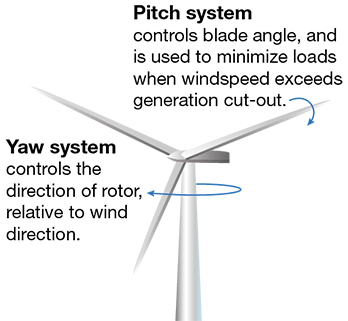
Figure 4: Pitch and Yaw Control of a Wind Turbine. Image Source: riskengineers.com
How to Create Your Own Micro-Wind Turbine
A micro wind turbine converts the wind’s kinetic energy into electrical current. Wind pushes the blades on the turbine, causing the rotor to spin. A generator converts this rotation into electricity. Motors can be used as a generator; to select the right motor, these specifications are important:
- Voltage: Choose a motor with the required voltage output.
- RPM: The motor should be able to generate electricity at low RPMs, so there is output even when there is little wind.
- Size/weight: Choose a motor with a size and weight that can be supported by your mounting structure.
When using a motor as a generator, a brushless motor (BLDC) can have an advantage over one with brushes. Brushes in brushed motors wear out and have to be replaced every once in a while. Brushless motors use magnets, which don’t wear out because there is no physical contact and friction. They are also typically more efficient. Brushless motors, however, require a 3-phase rectifier (See Figure 5) in order to convert the output they generate into a DC voltage. Brushed DC motors are able to generate a DC voltage directly.
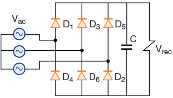
Figure 5: 3-phase rectifier circuit. Image Source: researchgate.net
Depending on the motor you use, you may also need a buck-boost converter to get the desired voltage. Various DC motors salvaged from old devices can work as generators, as well as an alternator from a car. This tutorial makes use of an old hoverboard.
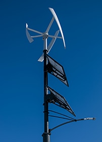
Figure 6: A Micro Wind Turbine Image Source: https://content.instructables.com
Now the fun part: cobbling together a windmill structure from pieces you can find at the local hardware store! Materials you’ll need:
- PVC pipes: Get a length of PVC pipe for the turbine blades and another for the tower.
- Steel pipe or metal rod: This will serve as the turbine shaft.
- Wooden board or base to mount the turbine.
- Wires and connectors
- Screws, nuts, and bolts: For assembling the components.
You’ll also need a battery to store the generated electricity. Larger projects might require a wind turbine charge controller to prevent overcharging of the battery.
- Design the blades: Determine the size and shape of the blades. The most common design is a simple flat or curved shape. Cut the PVC pipe into three or four equal-length pieces and shape them into blades using appropriate tools.
- Build the turbine hub: Drill a hole through the center of a small PVC cap that fits the motor shaft. Make sure it's tightly secured to the motor shaft.
- Construct the tower: Attach the PVC pipe for the tower vertically onto the wooden board or base. You can reinforce it with additional supports or a tripod if desired.
- Attach the blades: Connect the blades to the hub. You can use screws or epoxy to secure them in place, ensuring they are evenly spaced.
- Mount the motor and hub: Fix the motor and hub assembly to the top end of the tower using screws, ensuring the motor is facing the wind direction.
- Connect the wires: This step depends on the type of motor you are using. For a brushed DC motor, connect the output of the motor to the battery. For a BLDC, the output of the motor is connected to a 3-phase rectifier, then the battery.
- Test the turbine: Place the turbine in a location with a steady breeze or use a fan to simulate wind.
5. Glossary
- Airfoil: The shape of the blade cross-section, which for most modern horizontal-axis wind turbines, is designed to enhance the lift and improve turbine performance.
- Compressor: A mechanical device that increases the pressure of a gas by mechanically decreasing its volume.
- Drag force: Drag is the force generated parallel and in opposition to the direction of travel for an object moving through a fluid.
- Fuel Cells: A device that generates electricity through an electrochemical reaction.
- Generator: A device that produces electricity from mechanical energy, such as from a rotating turbine shaft.
- Grid: The utility distribution system. The network that connects electricity generators to electricity users.
- Lift force: It is the force generated perpendicular to the direction of travel for an object moving through a fluid (gas or liquid).
- Pitch: A system that regulates the wind turbine's power output by adjusting the rotor blades.
- Pulse width modulation (PWM): A modulation technique that generates variable-width pulses to represent the amplitude of an analog input signal.
- Rotor Hub: The center of a turbine rotor that holds the blades in place and attaches to the shaft. The rotor refers to both the turbine blades and the hub.
- Solenoid Valve: A solenoid valve is a type of valve that is controlled by an electric current.
- Supercapacitor: An electrochemical capacitor with high energy density and better performance efficiency than the normal capacitor.
- Tip Speed Ratio (TSR): The ratio between the wind speed and the tangential speed of the tip of the blades
- Turbulence: The changes in wind speed and direction, frequently caused by obstacles.
- Yaw: It is the component responsible for the orientation of the wind turbine rotor towards the wind.
*Trademark. Bulgin is a trademark of Bulgin Limited. Other logos, product and/or company names may be trademarks of their respective owners.
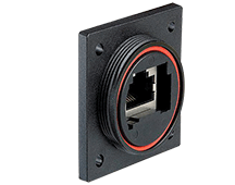
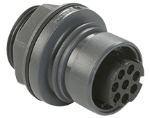
Bulgin offers a range of durable and reliable connectors designed for renewable energy applications, including wind power.
Test Your Knowledge
Power Skills 5
Are you ready to demonstrate your wind power knowledge? Then take a quick 10-question multiple choice quiz to see how much you've learned from this module.
To earn the Essentials Power 5 Badge, read through the learning module, attain 100% in the quiz at the bottom, and leave us some feedback in the comments section below.








Top Comments
-

md_steve
-
Cancel
-
Vote Up
0
Vote Down
-
-
Sign in to reply
-
More
-
Cancel
Comment-

md_steve
-
Cancel
-
Vote Up
0
Vote Down
-
-
Sign in to reply
-
More
-
Cancel
Children