


The demands for high efficiency, low loss, high power, and reliable safety are the major challenges in a modern power distribution system, from the power source all the way to the supplies for interconnected devices in a power network. These challenges have driven new developments in power distribution technology. Perhaps the newest development in power distribution is commonly termed as smart power distribution, which is a type of de-centralized power architecture based on multiple electronic and electrical modules rather than electromechanical devices such as fuses or relays.
Smart power distribution is well adapted to applications in transportation, aviation, robotics, and more. This learning module discusses the architecture, circuits, applications, and devices in a smart power distribution system for an automotive application.
Related Components | Test Your Knowledge 
2. Objectives
Upon completion of this module, you will be able to:
- Compare centralized and decentralized power distribution architectures
- Describe the essentials of smart power technology
- Understand the advantages of smart power switches in power distributiseon
- Discuss how smart high-side and low-side circuits operate
- Explain some applications of smart power switches
3. Basic Concepts
Designing power distribution architecture is a complex task, since it is usually customized to the application and requires an engineer to minimize the costs of the architecture to deliver power safely and efficiently under load variations. To fully understand the benefits of smart power distribution, let us start this learning module by discussing the two main categories of power distribution architecture: centralized and decentralized power distribution architectures.
3.1 Centralized power distribution architecture
Centralized power distribution architecture is designed to distribute electric power from the power source to individual systems in a network. In this architecture, control panels (i.e., master control), an associated main power source, power converters, Input/Output modules (Sensors, Relays, Actuators), and protection circuits for each device are usually located in a central location as shown in Figure 1.

Figure 1: Centralized power distribution architecture
The centralized system can monitor the individual systems or end applications (i.e. slave applications) from a single location. One disadvantage of a centralized system is the complexity of supply bus routing of circuits connecting the master and slave, which requires a significant amount of cabling to interconnect them. In addition, electrical efficiency is low due to increased distribution losses. An example of centralized power distribution would be traditional automotive power electronics, which operate on 12V batteries; the sensors and actuators are supplied with power through copper cables wired from a central power controller.
3.2 De-centralized power distribution architecture
De-centralized power distribution (also called distributed power architecture) is an architecture in which the system power requirements are divided into multiple intelligent power distribution centers (PDCs) spread throughout the vehicle. These PDCs communicate with each other via the vehicle's local interconnect network (LIN) or controller area network (CAN). Smaller power units or PDCs are both designed for and located near the operation of the devices in the system. A typical decentralized power architecture is shown in Figure 2.
This type of architecture reduces weight, not only in the wire harness but also by replacing the relatively heavy relays with small, modern, and light semiconductor devices. As well as reducing cost, the weight reduction that can be achieved improves fuel efficiency and makes a contribution towards the mandatory CO2 reduction. Further efficiencies are made possible by the fact that power losses in semiconductors are often a factor of seven times lower than a fuse / relay combination.
As the PDCs are able to communicate intelligently with each other, and with the rest of the vehicle, greater control and higher levels of integration are possible. This brings the potential for enhanced functionality and more intelligent and efficient use of energy. Combining this new type of architecture with advanced semiconductors brings huge benefits and addresses the deficiencies of the conventional electromechanical relay and fuse approach.

Figure 2: Block diagram of a decentralized power architecture
Decentralized architecture has significant advantages over the centralized model. It helps in standardization and customization of PDCs for each subsystem, so that the designer can pull together standard modules to design the power architecture. Any change in the system does not require a redesign of the entire power supply system as a whole, but only requires a change in the section that needs modification.
In contrast, a centralized power supply is bulky, as the higher power requirement needs large transformers and thermal management components such as heat sinks and cooling fans. In a distributed architecture, the source of heat generation is spread across all the modules, operating at reduced power levels. Therefore, the size of the transformers and heat sinks is substantially smaller, and, in many cases, cooling fans are eliminated.
A de-centralized architecture enhances the reliability of the power distribution system, since the electronic devices operate in a safer and less stressful environment. The efficiency increases substantially, since the conductors can carry power at high voltages and lower currents, which can be converted very close to the load points which require low voltage and high currents. Modern automotive electronics today are designed with a de-centralized power architecture where the 12V battery power is distributed throughout the vehicle and converted to various voltages and currents required for each system, sub-system, and device of the vehicle.
4. Smart power technology
Smart power distribution architecture provides periodic and real-time information for each PDC module in the system to supply the correct power for a specific function. It also provides feedback from its protective or supervisory circuitry to send an alert about possible risk factors or system malfunctioning.
Most smart power devices are DC-DC converters using buck/boost chopper or forward/flyback converter topologies. They have intelligent features, such as over-temperature, overcurrent, and short circuit protection circuitry that act locally and report current status back to the master control.
The system components need to have fast communication capability to provide real-time information to an intelligent master controller, which acts as a central data processing unit. The communication methods used typically are LIN, CAN, or Flex Ray interfaces (i.e. automotive network communications protocol).
The latest generation of smart power technologies are manufactured using standard CMOS processes, such as Silicon carbide (SiC) technology or Gallium nitride (GaN), and possess built-in self-protection circuitry, on-chip control circuitry, and an interface to external logic circuits which are suitable for industrial and automotive applications. Figure 3 shows the internal block diagram of smart power switch.

5. Fuse and Relay Replacement in Smart Power Distribution
In conventional power distribution systems, relays connect or disconnect the power source to/from a load when an external analog voltage enable signal is applied to the relay from the controller. As such, when a relay is energized, source current flows through the load; when it is disconnected, the circuit opens.
Despite being widely used, relays are not the perfect switch, since they require more voltage to turn on, are unregulated, and involve higher electromagnetic losses. The advent of smart power switches opens the door to the replacement of relays with semiconductor switches.
5.1 Replacing Relays with Semiconductor Switches
During the past decade, semiconductor switches have been replacing electromechanical switching devices (i.e., relays) in low power load applications such as automotive body control modules. However, replacing relays and fuses in high current loads such as engine cooling, windscreen defrosters, vacuum pumps for electric brakes, and control unit switches has been more of a challenge. Relays are vulnerable to arcing at high switching cycles, reducing the reliability of the system.
But now, with the availability of smart power devices, the design of these systems is changing. Smart switches (e.g., MOSFET, IGBT, FET, etc.) turn on at low voltages, enabled by PWM control signals, have a very high current capacity (up to 40A), and extremely low on-resistance (down to 1.0m Ω). These devices are providing high energy capacity of around 3000mJ, enabling them to replace relays in higher load applications. Semiconductor switches also reduce the losses and the overall power dissipation, thereby increasing the lifetime use and reliability of the system.
5.2 Replacing Traditional Fuses with Reprogrammable Fuses
In a relay switching system, protection is provided by using cut off fuses, which permanently interrupt current flow at the instance of the overload fault condition. A fuse box is critical to the system, and it’s usually located at an accessible and central location so that the fuses can be replaced to restart the system when the fault condition is eliminated. A complex wiring harness is required, since fuses must be interconnected to the loads.
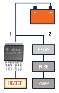
Figure 4: Replacement of a relay and fuse with a PROFETTm smart switch
A traditional fuse can be replaced with a smart power switch, which acts like a reprogrammable fuse and can be reset by software automatically when the fault condition is cleared. Figure 4 illustrates how a smart switch in a decentralized power distribution architecture can replace an electromechanical relay and traditional fuse in an electric vehicle.
6. Smart Switch Configurations
Smart switches connect or disconnect a power source (i.e., battery) to/from a load. Depending upon the location of the switches in the power circuit, they are defined as either high-side or low-side switches.
6.1 High-side switches
High-side switches connect or disconnect power to a load depending on the control voltage provided by the controller. They are connected between the positive power line and one end of the load. The other end of the load connects to ground. High-side switches can safely drive high currents into resistive, inductive, and capacitive loads in compliance with harsh automotive environments, requiring both robust, low on-resistance power switch and accurate analog circuitry used for diagnostic, protection, and control functions. High-side switches are used in automotive systems such as junction boxes, interior/exterior lighting, DC motor drives, and more.
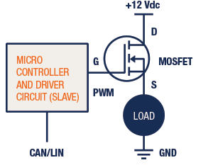
Figure 5: High-side switch circuit diagram
A simple application circuit using a MOSFET and load is shown in Figure 5. In this circuit, the high-side switch acts as a linear power controller. The local controller, a slave device, receives the signal from the master controller and produces a suitable PWM signal. The gate drive circuit amplifies the controller output and feeds it to the MOSFET. High-side switches support decentralized vehicle power distribution architectures.
6.2 Low-side switches
Low-side switches connect between one end of the load and ground. With the ability to switch high currents safely, low-side switches provide load control switching to ground for resistive and inductive loads depending on the control voltage. These switches are convenient for driving LEDs, relays, and motors. A simple application circuit using a MOSFET and load is shown in Figure 6. The controller or slave device receives the signal from the master controller and produces an on-off signal. If the controller gives an ON signal to the MOSFET switch, it conducts current flow through the load and MOSFET to ground.

7. Applications
There are numerous applications for smart switches, with motor and LED drivers being two of the most common ones. But there are other applications of smart switches in power distribution that characterize both new and interesting uses of these devices. In this section, we will discuss three of them: smart battery switches, decentralized power distribution centers, and power net management systems.
7.1 Smart Battery Switches
A smart battery switch is an electronic high-current battery disconnect, built with ultra-low ohmic TO-Leadless (TOLL) MOSFETs in combination with an innovative Inlay PCB technology (multilayer PCB combined with thick copper inlays). They have very high current-carrying capability, low resistance, excellent thermal resistance and heat spreading, high mechanical stability, and are automotive qualified. They have a static current capability of 250A (36K ∆T) and support starter peak currents up to 1800A.
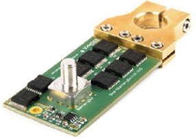
Figure 7: Smart Battery Switch
Smart battery switches have been designed to replace pyro-electric battery disconnect switches or to provide a safety switch for high current loads (e.g., EPS, engine fan, chassis control). Additionally, they can be used for quiescent current optimization (e.g., parking, transport, seasonal use), or resettable failure current shutdown (e.g., electro-migration, corrosion).
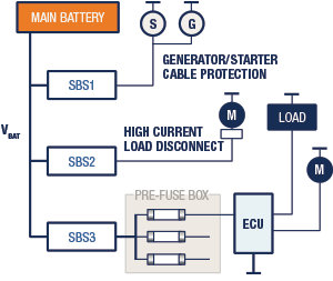
Figure 8: Smart Power Distribution with Smart Battery Switches (SBS1-3)
7.2 Decentralized Power Distribution Modules
Needless to say, smart power distribution architectures are evolving. A good example of this evolution is a decentralized architecture, where multiple intelligent power distribution centers (PDCs) are placed throughout the vehicle (Figure 9). While the basic architecture within the PDC will remain the same with respect to control and communications interfaces, scalable semiconductors will allow for a range of higher or lower power PDC modules with a common 'core'. This commonality brings cost benefits in terms of economy of scale as well as reliability.
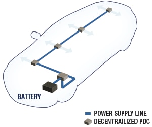
Figure 9: Block Diagram of Smart Power distribution systems with decentralized PDCs
PDCs can be mounted almost anywhere in the vehicle. And, as there is nothing inside for the driver to service or replace, access is not required. This simplifies and reduces wire harnesses, saving weight and cost. As each PDC is microprocessor-controlled, functionality can be easily adapted in software and the PDC operation can be configured to suit different models of vehicle with varying options (Figure 10). Service updates to software can be implemented via a dealer network, ensuring that older models of vehicle benefit from the latest developments.
Figure 10 is a prototype PDC using multiple Infineon switches to serve a total of six loads. BTS50015- 1TAA and BTS50045-1TAA are Power PROFETS with 1.5 mΩ and 4.5 mΩ on-state resistances, respectively. The BTC50010-1TAA is a Connect FET that, via a pin, controls the companion transistor BTC30010-1TAA connected in parallel, serving to reduce the on-state resistance by half. The BTS5090-1EJA is a 90 mΩ switch from the PROFET+ family.
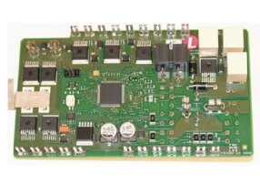
Figure 10: A prototype PDC where semiconductors have replaced relays and fuses
As can be seen in Figure 10, not all relays were replaced by semiconductor switches. One reason for this was to prevent a reverse load current being generated when the polarity reverses at the inverse diode in the semiconductor switch. This can be suppressed either by a pair of semiconductor switches connected in anti-series or a central relay with normally closed contacts that blocks the current when the polarity reverses.
A further relay operating as a redundant switching element combined with a semiconductor switch was mounted at the starter switch. In this combination, the semiconductor switch provides the high cycle counts and wire protection, and the relay functions as a redundant cutoff option and reverse polarity protection. The relays were actuated in series with a constant current relay driver (TLE4247 from Infineon). This facilitates a regular coil current when the relay is switched on. Once the relay is energized, the current is reduced to the holding value, thus reducing the power loss in the relay coils. Having migrated to semiconductors, the actuation and diagnostics for these devices have to be implemented by microcontrollers integrated directly into the PDC. This also requires a voltage supply (TLE4675) and CAN communication (TLE6251DS) to communicate with other controllers. The additional cost of these devices is partly offset by the elimination of relay control wires.
7.3 Power Net Stabilizer for Stop-start Systems
Automotive Stop-Start systems automatically shut down and then restart the engine to decrease the time an engine is idling, which in turn reduces fuel consumption and emissions. Despite the benefits of stop-start systems, they are a challenge for the power net, which needs to be stabilized during the stop/start transition. A board net stabilizer using a smart power switch can disconnect the starter and main battery from the auxiliary electrical systems during engine start (Figure 11). It uses a high side Mosfet driver connected as a back to back switch, featuring a very low quiescent current both on and off state. The AUIR3241S is a combination of a boost DC/DC converter using an external inductor and a gate driver (Figure 12). It drives standard level Mosfet even at low battery voltage. The input controls the gate voltage. The AUIR3241S integrates under voltage lock out protection to prevent driving the Mosfet in linear mode.

Figure 11: The power net stabilizer demo board
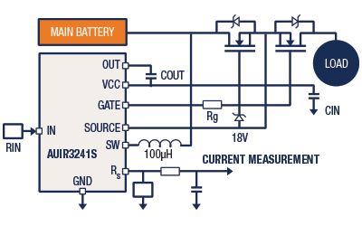
Figure 12: Typical connection: Back to Back Switch
*Trademark. Infineon is a trademark of Infineon Technologies. Other logos, product and/or company names may be trademarks of their respective owners.
Shop our wide range of smart switch products, including development kits, demonstration boards, Mosfets, Gate Driver ICs, IGBTs, DC/DC Converters, IPMs, and smart low-side & high-side switches.
Test Your Knowledge
Power Skills 4

Are you ready to demonstrate your Smart Power Distribution knowledge? Then take this 10-question quiz. Then take a quick 15-question, multiple-choice quiz to see how much you've learned from this Smart Power Distribution Learning Module.
To earn the Smart Power Distribution knowledge badge, read through the module, attain 100% in the quiz at the bottom, and leave us some feedback in the comments section.


Top Comments