Audio Amplifiers amplify input audio signals to voltage and power levels required by the speaker element of an audio system. In the 1960s, audio amplifiers were made of vacuum tubes and transformers, which were replaced with solid state devices like BJTs, FETs, and MOSFETs in the 1970s. Today's audio amplifiers use highly efficient ICs capable of producing high fidelity sound in small and lightweight packages. In this learning module, we cover the essentials of audio amplifier ICs, with a focus on the most popular Class-D amplifiers, their characteristics, output filter design, and applications.
Related Components | Test Your Knowledge
2. Objectives
Upon completion of this learning module, you will be able to:
- Understand the basic concepts, architecture, and characteristics of audio amplifiers
- Explain the different classes of audio amplifiers
- Discuss the output filter design for Class-D audio amplifiers
- Describe Class-D audio amplifier applications
3. Review
An audio amplifier is a type of operational amplifier that has a number of stages to deliver enough power for an output device such as a loudspeaker. Audio amplifiers are also known as power amplifiers, which amplify both voltages and current. To review the operation, connection, configurations, and characteristics of op-amps, please visit the two previous learning modules in this series: Low Power Op-Amps and Specialty Op-amps for High Voltage and Precision Applications.
4. Characteristics
The following are essential characteristics of an audio amplifier:
5. Classes
Amplifiers are classified in two groups:
- Group 1: The first group is based on the proportion of each input cycle during which an amplifier passes current (conduction angle). The group consists of Classes A, B, AB, and C.
- Group 2: The second group consists of switching amplifiers based on digital circuits and pulse width modulation (PWM). This group consists of Classes D, F, G, I, S, and T.
In this section, let us discuss the most common classes of audio amplifiers in more detail.
- 5.1 Class-A Amplifier
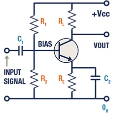
Figure 1: Example of a Class-A Amplifier
Class-A amplifiers consist of a single transistor that is connected in a common emitter configuration. It is more linear compared to other classes and produces a less distorted output. The major disadvantage of Class-A amplifiers is the low efficiency, which is typically less than 35%. Even if there were no bias signal, all output devices would conduct over the complete cycle. It results in significant amounts of power loss, heat dissipation, and a decrease in efficiency.
- 5.2 Class-B Amplifier
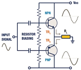
Figure 2a: Example of a Class-B Amplifier
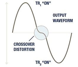
Figure 2b: Output Waveform and Crossover Distortion
The Class-B amplifier uses NPN and PNP transistors as shown in Figure 2A. Each transistor is active in only one-half cycle, with a 180° conduction angle of the input signal. Since it dissipates less power, efficiency is improved, typically to 78.5%. Class-B amplifiers reduce the heating problem associated with Class-A. In addition, Class-B amplifiers have a higher gain than Class-A amplifiers. The transistors conduct only when the input signal is higher than the base-emitter voltage. Therefore, no power is consumed at zero input. The disadvantage of a Class-B amplifier is the crossover distortion as it uses complementary transistors for each half of the waveform (Figure 2B).
- 5.3 Class-AB Amplifier
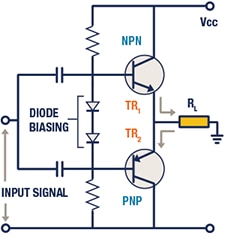
Figure 3: Example of a Class-AB Amplifier
The Class-AB amplifier combines the advantages of both Class-A and Class-B configurations. The biasing is achieved by the forward voltage drop of the two compensating diodes, as shown in Figure 3. Both transistors slightly conduct without any input signal and eliminate any crossover distortion present in Class-B amplifiers. For low power outputs, this design operates as a Class-A amplifier, and for larger current outputs, it changes to a Class-B amplifier. Its efficiency is less than 78.5%.
- 5.4 Class-D Amplifier
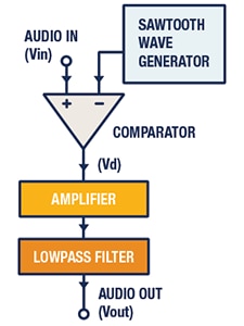
Figure 4: Class-D amplifier block diagram
The Class-D amplifier is a switching amplifier or a pulse width modulation (PWM) amplifier. Figure 4 shows a basic Class-D amplifier block diagram. The comparator modulates the audio signal with the sawtooth waveform generated by the wave generator circuit. The comparator output is the modulated digital form of the analog input audio signal. This digital signal is fed to the switching stage to amplify the signal further to drive speakers. A low pass filter reshapes this signal back to its analog shape.
Class-D amplifiers feature low noise, low distortion, wide bandwidth, and high-power output. The Class-D amplifier minimizes power consumption and thermal dissipation. Its efficiency is greater than 90%.
6. Class-D Modulation
In a Class-D amplifier, the input audio signal is converted into a PWM signal using modulation. A PWM signal is constructed by comparing the audio input signal to a triangular reference signal. This reference signal has a higher fundamental frequency (or carrier frequency) than the audio signal. The PWM is classified as AD modulation and BD modulation.
- 6.1 AD Modulation
In this technique, the carrier signals are in opposite phases as shown in Figure 5. There is no common-mode signal, since both outputs switch simultaneously in the opposite directions. Common-mode DC voltage is generated due to the average value of the PWM switching. This DC voltage appears on both sides of the load. Hence, there is no power dissipation across the load.
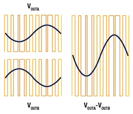
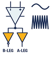
Figure 5: AD modulation in BTL Class-D Amplifier
The amplifier switches at the PWM frequency with a 50% duty cycle across the load, which causes significant current flow and power dissipation into the load. So, an LC filter is necessary to decrease the current and to provide better efficiency.
To further improve the efficiency of Class-D amplifiers, TI developed a proprietary modulation scheme, implemented in the high-power TPA3221 Class-D amplifier called High-Efficiency AD modulation (HEAD). To learn more, please visit the Related Components page of this learning module. HEAD modulation differentiates itself with benefits such as reduced idle power losses, improved EMI performance, and less pop noise. These benefits make HEAD useful in wireless speaker applications.
- 6.2 BD Modulation
In this technique, the carrier signals are in the same phase as shown in Figure 6. This modulation has common-mode content in its output.
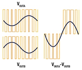
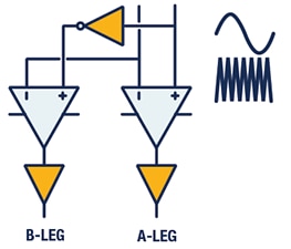
Figure 6: BD Modulation in BTL Class-D Amplifier
The BD modulation switching technique modulates the duty cycle of the difference of the output signals such that its average signal corresponds to the input analog signal.
- 6.3 Hybrid Modulation
Hybrid Modulation is designed for minimized power loss without compromising the THD+N performance, and is optimized for battery-powered applications. With Hybrid modulation, TAS5825M detects the input signal level and adjusts the PWM duty cycle dynamically based on PVDD. Compared with traditional PWM modulation, hybrid modulation dynamically maintains differential switching with several common duty options. Hybrid modulation achieves ultra-low idle current and maintains the same audio performance level as BD Modulation. The benefits of Hybrid PWM modulation include:
- Higher efficiency for longer battery lifetime
- Good THD+N performance
- Ultra-low idle power dissipation and idle noise
7. Class-D Configurations
Class-D audio amplifiers often support multiple output configurations in a single device, which provides added flexibility for the end application. In this section, let us discuss three common configurations of Class-D amplifiers.
- 7.1 Bridged-Tied Load (BTL)

Figure 7: Stereo (Two-Channel) BTL Class-D Amplifier
In the BTL configuration, one amplifier drives one side of the load and gives an inverted signal to the other amplifier, which drives the other side of the load. It results in twice the voltage swing across the load and quadruples the power (P = V 2 / R). The voltage across the load must be measured differentially because the load is not ground-referenced.
- 7.2 Parallel Bridge-Tied Load (PBTL)
A Parallel Bridged-Tied Load (PBTL) is an output configuration that takes a stereo BTL amplifier and connects the outputs in parallel for a mono channel. In this configuration, the output voltage is the same, but the output current is doubled because each output shares the load current. The PBTL often allows lower-impedance loads to be driven with higher output power when compared to a BTL of the same supply voltage.
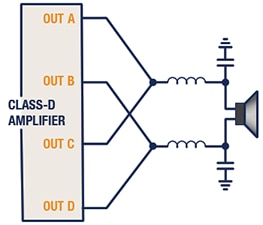
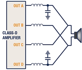
Figure 8: PBTL Class-D Amplifier, Output Configurations
- 7.3 Single-Ended (SE)
In a single-ended (SE) configuration, only half of the signal swing is available because only one output is used to drive the load. However, this configuration can allow for four channels with a single stereo BTL amplifier as shown in Figure 8. Some amplifiers also allow a combination of one BTL and two SE channels for support of 2.1 audio systems with a single device.
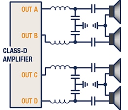
Figure 9: Four Single-Ended Outputs
The PWM modulation introduces a DC voltage equal to half of the supply voltage at the output of the LC filter. The speaker is referenced to ground. A DC blocking capacitor is required to avoid the DC voltage across the speaker.
8. Protection
Excess voltage, current, temperature, and other factors like electromagnetic interference beyond the specification/rating of the amplifier device can damage it and impact performance. This is one of the reasons why Class-D audio amplifiers are integrated with system protection; these features help to create reliable audio designs. In this section, let us discuss some of the integrated protection features.
Overcurrent Protection:
Class-D amplifiers feature overcurrent protection. When the output current exceeds the threshold limit, the amplifier is shut down, and sends a signal to the host processor. In addition, some amplifiers offer cycle-by-cycle current (CBC) limit, which instead of shutting down will adjust the output cycle by cycle, so if it is just a temporary peak, the amplifier will keep playing instead of shutting down. More information on this feature can be found here: Overload and Short Circuit Current Protection.
Over-Temperature Protection:
Each Class-D amplifier has temperature limitations specified by the manufacturer. Exceeding those limits results in overheating of the device. When the temperature of the amplifier exceeds a specified level, the amplifier shuts down to prevent overheating. Some amplifiers have more sophisticated thermal protection; they send a warning to the host before shutdown so they can reduce the gain or prevent the thermal shutdown. For example, the TAS5825M supports thermal foldback, which actually has 4 levels of warnings at different temperatures to give several chances at adjusting the output to prevent thermal shutdown.
Amplitude Modulated (AM) Interference Avoidance:
Certain switching frequencies introduce AM interference and harmonics affecting the performance of the amplifier. This AM avoidance feature allows the designer to program the switching frequency of the amplifier to avoid the interference.
Voltage Protection:
Irregular power line conditions such as over voltage, under voltage, voltage fluctuations, overload, and short circuits can damage silicon devices. Protection against these faults is built into Class-D amplifiers.
Automatic Gain Limiter (AGL):
Because of input signal variations, the output of the amplifier may cross the supply rails, resulting in clipping of the output which would affect the audio integrity. Class-D amplifiers feature an automatic gain limiter to linearly vary the gain and compress the signal amplitude when the output exceeds a specified threshold voltage.
DC Offset Protection:
Short circuits or the presence of rail voltage directly in the amplifier output may cause damage to the speaker. The DC offset protection circuit continuously receives PWM input signals from the outputs and inspects for any large DC voltage difference which is being reflected on the speaker load. If so, the circuit triggers a channel shutdown signal when the DC offset reaches a preset level.
Excursion Control:
An excursion is a distance that the speaker diaphragm moves in and out from its resting position which is controlled to avoid damage to the speaker. Amplifiers control the excursion via current and voltage sense feedback circuits.
Coil Temperature:
When a speaker plays audio, an amplifier generates heat due to power dissipation. The speaker coil can heat up beyond the specification and get damaged. Amplifiers can be shut down by monitoring the temperature also via current and voltage sense feedback.
9. Output Filters
- 9.1 Type-1 Filter
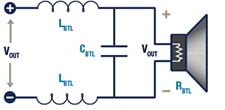
Figure 10 - Type-1 Filter for AD Modulation
The Type-1 filter is a differential filter which is used for AD modulation (Figure 10). AD modulation has no common-mode content on its outputs, and thus only the differential mode is needed for analysis.
- 9.2 Type-2 Filter
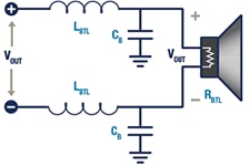
Figure 11: Type-2 Filter for AD or BD Modulation
The Type-2 filter is a common-mode filter designed for BD or AD modulation amplifiers (Figure 11). Type-2 filters are common mode and can easily convert into their equivalent single-ended form.
- 9.3 Hybrid Filters
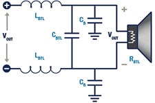
Figure 12: Hybrid Filter for AD Modulation
For some applications, it is beneficial to use a hybrid filter as shown in Figure 12. It combines Type-1 and Type-2 filters for an AD modulation amplifier.
- 9.4 Inductorless Filters
An inductor-less solution, using ferrite bead filters, can be implemented to reduce board space and system cost. For example, the TAS5805MEVM has an inductor-less solution implemented on one amplifier and normal inductors on the other. See the Related Components page of this learning module.
10. Applications
In this section, we feature two Class-D amplifier applications to illustrate examples of the use of audio op-amps in real applications.
- 10.1 Type-1 Filter
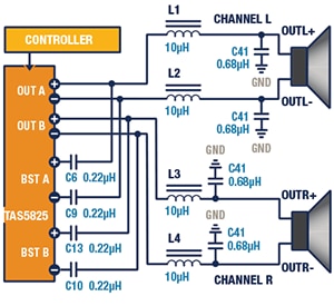
Figure 13 - 2.0 (Stereo BTL) System Application Schematic
The TAS5825M is a high-performance, stereo closed loop Class-D with an integrated audio processor with up to 192-kHz architecture. In this 2.0 system (Figure 13), the amplifier provides two channels via the digital input signal. These two channels are amplified and then sent to two separate speakers. In some cases, the amplified signal is further separated based upon frequency by a passive crossover network after the L-C filter. The two channels are called a stereo pair, with one channel containing the audio for the left channel and the other channel comprising the audio for the right channel.
- 10.2 Differential AD-Mode PBTL System
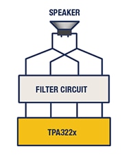
Figure 14 - Typical Differential AD-Mode PBTL Application
The TPA3220 is a pad-down Class-D amplifier that enables efficient operation at full-power, idle, and standby. The device features closed-loop feedback with a bandwidth up to 100 kHz, which provides low distortion across the audio band and delivers excellent sound quality. The device operates with either AD or low idle-current HEAD modulation. The TPA3220 also achieves higher than 90% efficiency, low idle power (< 0.25W), and ultra-low standby power (< 0.1 W). It is made possible through the use of 70-mΩ MOSFETs, an optimized gate drive scheme, and low-power operating modes.
*Trademark. Texas Instruments is a trademark of Texas Instruments Inc. Other logos, product and/or company names may be trademarks of their respective owners.
Shop our wide range of audio operational amplifiers, including low power, ultra-low noise, low THD+N, and small package op amps, as well as associated development boards.
Test Your Knowledge
Op Amps III
Are you ready to demonstrate your Audio Op-Amps knowledge? Then take a quick 15-question, multiple-choice quiz to see how much you've learned from this module.
To earn the Op Amps III: Audio Op-Amps Badge, read through the module, attain 100% in the quiz at the bottom, and leave us some feedback in the comments section.



Top Comments
-

jc2048
-
Cancel
-
Vote Up
+5
Vote Down
-
-
Sign in to reply
-
More
-
Cancel
-

rusgray
in reply to jc2048
-
Cancel
-
Vote Up
+3
Vote Down
-
-
Sign in to reply
-
More
-
Cancel
Comment-

rusgray
in reply to jc2048
-
Cancel
-
Vote Up
+3
Vote Down
-
-
Sign in to reply
-
More
-
Cancel
Children