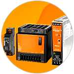
Industrial power supplies are an essential component of electrical control panels used in today's manufacturing and production process equipment. While many design engineers, control panel builders, and systems integrators already know the unique functions of industrial power supplies, the ever-changing and expanding functionality of industrial power supplies with respect to control systems technology merits further discussion. While industrial power supplies are part of the broader category of switch-mode power supplies (SMPSs), they now offer enhanced features to improve machine reliability, electrical safety, and parallel redundancy for the components and systems they power. Beyond these factors, industrial power supplies can future-proof the capabilities needed for the evolving infrastructure of industrial digitalization, the smart factory, and Industry 4.0 initiatives. This learning module will cover the essentials of industrial power supplies, including basic concepts, types and applications.
Related Components | Test Your Knowledge
2. Objectives
Upon completion of this module, you will be able to:
- Understand the basic concept of a power supply
- Explain how a switch-mode power supply operates
- Describe the types and topologies of switch-mode power supplies
- Discuss some applications of an industrial SMPS
3. Scope
A power supply is fundamental to any automated production process. Industrial power supplies typically convert high voltage AC to low voltage DC to power programmable logic controllers, I/O, and HMI devices. Older and bulkier linear power supplies have been replaced by today's highly efficient switch-mode power supplies featuring smaller form factors and direct parallel connection through integrated ORing MOSFETs.
Any discussion on industrial power supplies should cover the desired characteristics to consider when selecting a power supply, such as sizing requirements; integrated overcurrent, short circuit, and over temperature protection; power factor correction; the need for Lower THD to obtain higher power factor, better efficiency, and lower peak currents; electromagnetic compatibility (EMC) to minimize electromagnetic interference (EMI); and ingress protection ratings for their operation in hazardous environments.
But what is the difference between a power supply used for consumer electronic use and an industrial power supply used in mission-critical applications at Class 1 Div 2 (potentially explosive environments) production sites, or even in extreme temperatures ranging from - 40°C to + 70°C? In this learning module, we will limit the scope to focus first on a refresher of switch-mode power supplies, and then delve into the key differentiating characteristics of an industrial power supply.
4. Basic Concepts
The electricity we use in our homes and office buildings is commercial "mains" AC power sourced from the electricity grid generated at centralized power plants. However, the AC voltage cannot directly operate the integrated circuits and electronic components used within office equipment, factory automation equipment, and other consumer electronic devices. Stable DC voltages are necessary to operate these devices and integrated circuits. A regulated DC power supply is a device that converts commercial AC to regulated DC power.

Figure 1: Power Supply Block Diagram
Power supplies can be separated into two broad categories: Switch-Mode Power Supplies (SMPSs) and Linear Regulated Power Supplies (LPSs). An LPS initially transforms high AC voltage to low AC voltage, which is then rectified. The output voltage is regulated by relinquishing excess voltage.
A switch-mode power supply (SMPS) employs semiconductor switching techniques, and is more complex than a linear power supply. An SMPS receives commercial AC power at its input and uses a high-frequency power switching stage and a control circuit. It shifts between fully ON and entirely OFF states at an extremely high frequency. The power switching stage performs the power conversion from the circuit's input voltage to its output voltage, including output filtering. The switch-mode operation ensures a regulated DC supply output, and is more efficient for a prescribed size, weight, and power unit cost.
- 4.1 The Basic Operation of an SMPS
An SMPS maintains a constant output independent of load variations. It can buck, boost, or buck-boost the output voltage, which makes it superior to linear regulators, which can only decrease or buck the output voltage.

Figure 2: Block Diagram of an SMPS
Figure 2 illustrates how an SMPS functions. In the first stage, the input AC power is applied to the rectifier and input filtering to generate DC power. The second stage sees the SMPS working at high frequencies. The high-frequency switch enables a high-frequency pulsating DC signal. The SMPS switching regulators continuously alternate between on and off states. The high dissipation state, which reduces system power dissipation, takes minimal time. In the third stage the power transformer steps down the voltage. The stepped-down signal is subsequently rectified and then filtered to provide a constant, steady DC output. The control circuitry maintains a steady output of the desired voltage level.
- 4.2 Types of SMPS
SMPSs are classified according to their input and output type voltages. They can be AC-to-DC, DC-to-AC, DC-to-DC, and AC-to-AC supplies. In this section, we will limit our discussion to the two most common types: AC-to-DC and DC-to-DC.
AC-to-DC (Single and Three Phase) SMPSs
A single-phase AC power supply is generally capped off for domestic use at a nominal 120V or 240V, depending on the region or country. For industrial use, a three-phase AC input is around the 400V AC in Europe, and 210–270V AC in the US. These voltages vary significantly by configuration and application. Voltage ranges of 525–600V AC or even 690V AC are occasionally encountered. Although they both share the same overall working principle, the circuit design of a Single Phase SMPS and a Three Phase SMPS have some minor differences.
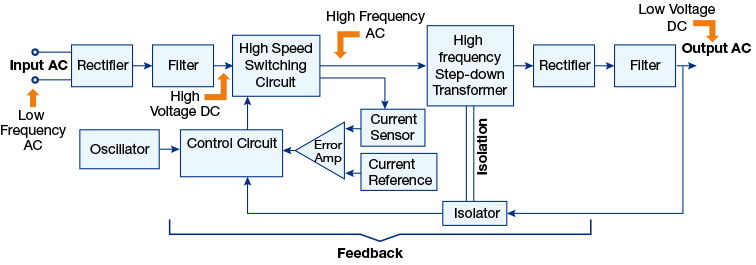
Figure 3 (a): Single-phase AC-DC SMPS block diagram

Figure 3 (b): Three-phase AC rectifier replacement circuit
A single phase SMPS block diagram is illustrated in figure 3a. The high voltage AC supply is sent to the rectifier and filter circuitry to convert it into high voltage DC. The supply subsequently is applied to a Power MOSFET or a High-Speed Switching Element. The high voltage pulsating, high-frequency AC output of the MOSFET is sent to a High-Frequency Step-down Transformer. The transformer output is a Low Voltage AC signal, which is then sent to a rectifier and filter to obtain Low Voltage DC.
The three-phase design topology uses six diodes in a diode bridge circuit, as shown in Figure 3b. The two diodes conduct simultaneously, with each diode conducting for 120 degrees in a full cycle.
DC-to-DC SMPSs
In a DC-to-DC SMPS, the DC input power is directly provided from a DC power source. This DC power is then switched at an extremely high rate, with a 15 kHz to 50 kHz switching speed. It is then fed to a step-down transformer. The step-down transformer output is then fed into the rectifier and filter circuit. A sample of the output DC power is employed as feedback to control the output voltage. This feedback voltage is used to control the oscillator ON time, and creates a closed-loop regulator. A PWM (Pulse Width Modulation) switching technique regulates the switching-power supply output.
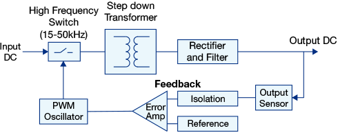
Figure 4: DC-to-DC SMPS Block diagram
- 4.3 SMPS Topologies
There are a variety of topologies used in SMPS designs. A specific topology may be favoured based on performance criteria such as cost, efficiency, output power, overall weight, and size. It is vital to know the elementary operation, complexity, advantages, drawbacks, and application of a specific topology for a given specification. In Table 1, we compare the key features of various SMPS topologies.
Table 1: SMPS Topologies
5. Analysis
While a DC power supply by definition converts AC or DC input power to the correct output voltage and current to power an electronic or electrical load, an industrial power supply possesses enhanced features for use in demanding operations, as well as providing communication capabilities to support data processing for condition monitoring, process optimization, or maintenance planning in automation or Industry 4.0 systems. To illustrate the difference between a standard and industrial power supply, we will use as an example the Weidmüller PROtop Industrial Power Supply. In this section, we will discuss the differentiating features of a high-end industrial power supply and then discuss some critical applications.
- 5.1 Differentiating Characteristics
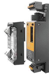
Figure 5: WeidmÜ PROtop Industrial Power Supply with communication module
While high-efficiency, good line-to-load regulation, electrical isolation, and thermal management are factors common to most power supplies, there are some key features that differentiate a PROtop industrial power supply from conventional DC power supplies:
- Dynamic current limiting technology to provide peak load reserves during triggering of circuit breakers or handling inrush currents during DC motor starting
- High efficiency—more than 95% through the use of field effect transistors that consume a negligible amount of energy for switching
- Integrated ORing MOSFETs for system redundancy without the need for diode modules
- Communication-capability for use in networked production and Industry 4.0, advancing manufacturing for process optimization and condition monitoring
- IP20 to IP65 ratings, with flexible enclosure kits, for use in hazardous environments
- 5.2 Applications
In this section we will discuss several applications where an industrial power supply like the PROtop outperforms conventional power supplies for use in challenging industrial environments.
DC Motor Starting
Production machinery needs to be reliable, even during demanding situations. One of those situations is DC motor starting, a commonly used drive component in industrial processes. DC motors characteristically have very high starting or inrush currents, depending on the application, which can often be many times more than rated full load amps (nameplate). Most DC power supplies do not offer this extra power to handle inrush currents. The typical solution has been to use an oversized power supply to support the inrush currents, which in essence provides reliability protection in order to avoid a drop in voltage (during motor starting) to all the other loads connected to the power supply; however, utilizing an oversized power supply has some drawbacks. Besides the added cost, an oversized supply increases the footprint, which can be an issue for small control panel cabinets.
A different solution to this problem is to employ a DC power supply like the PROtop that incorporates DCL (Dynamic Current Limiting) technology, which maintains a constant output voltage even if the load requires 6 times the rated current (for a short time), or 130% of the rated current (continuously), or any value between these limits. The high pulse reserves for starting motors translates into machine reliability. In case of inrush currents, the PROtop power supply has an energy reserve which is not limited in time, but in power delivered to the load (square of electrical current x time). This means different motors - or loads - with different curves will request their own inrush current and the power supply will adjust itself dynamically to cover the demand of each one.
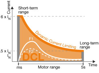
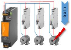
Figure 6: The dynamic current limiting of the PROtop trips magnetically a downstream circuit breaker (gray column in graph above) and supplies the inrush current of DC motors (white line in graph above), keeping the voltage to other loads.
Circuit Protection During Short Circuit Fault
Another issue to address is the triggering of circuit breakers in the DC lines. If there is a short circuit anywhere in the DC supply system, and a device is connected to protected lines, then protection circuits should work to cut off the power supply to the defective line. However, to operate properly these protection circuits also need extra power for a short period of time. Most power supplies do not offer this extra power reserve. The common solution in the past was also to install an oversized power supply. (This is similar to what has been done to deal with very high starting currents during DC motor starting.) But oversizing the power supply increases footprint in the electrical cabinet, as well as adding to the overall cost. By contrast, the Dynamic Current Limiting technology of a PROtop industrial power supply keeps the output voltage constant even if the load requires 6 times the rated current (for a short time), 130% of the rated current (continuously), or any value between these limits.
Thus, during a short circuit, the Dynamic Current Limiting technology can sustain the operation of the power supply even if the short circuit occurs in the automation system. Basically, the limit of the power supply is defined by the energy stored inside internal transformers and capacitors. If a DC branch requests high current, the DCL technology enables the PROtop power supply to spend up all the available current. This condition is kept for a few milliseconds to give enough time and energy for the protection of the damaged line to actuate. If there is no protection in the line, the power supply will return to rated current or it will shut down, according to the user's choice.
Decoupling Redundant Parallel Power Supplies
The concept of redundancy is critical when it comes to power supply units used for industrial processes. Equipment failures due to loss of power means downtime for machinery and slowdown or complete shutdown of the processes. In the past, redundant parallel power supplies were decoupled by using rectifying diodes, often called Diode Modules. The downside of diode modules is that they not only limit available space in electrical control panels, but the diodes themselves consume power, thereby reducing efficiency. To overcome these drawbacks, PROtop power supplies replace diode modules with integrated ORing MOSFETS, and the field effect transistors (MOSFET) act as rectifying diodes to ensure the current only flows in one direction, and the voltage at the output from the diode will be kept more stable. The integrated ORing MOSFETs in the PROtop provide high power with minimal dimensions and do not require any additional assembly or wiring work. This reduces system costs and saves space in the control cabinet. The parallel operation option makes current sharing easier and guarantees maximum long-term stability. This is crucial for providing the same output current parameters from each power supply when they are operating in parallel.
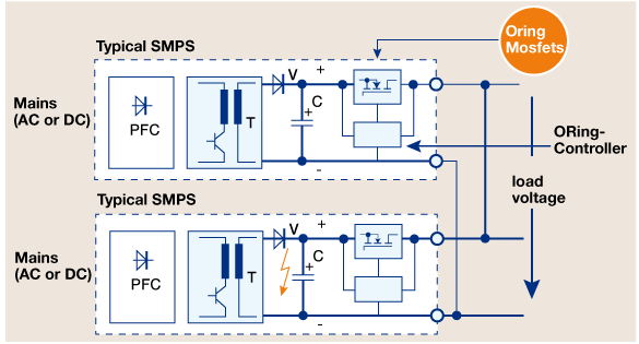
Figure 7: Integrating ORing MOSFETs Technology
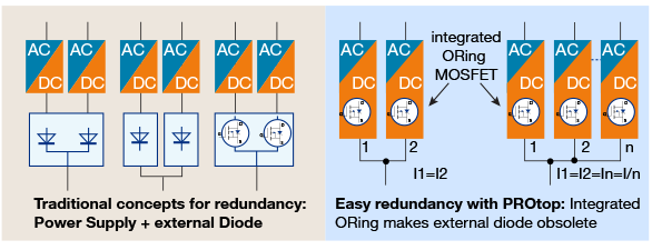
Figure 8: Standard Power Supply with redundancy vs. PROtop with redundancy: External diodes are no longer necessary.
Remote Operation and Data Communication
Whether it be a hazardous or remote environment that's not safely or geographically accessible, it is useful to be able to remotely operate a power supply, as well as being able to monitor conditions. The PROtop power supply can be retrofitted with a communication module (CANopen and IO-Link communication protocols) to enable it for both of these capabilities. The communication module allows simple integration of process data into the higher-level control system for improved condition monitoring. It enables remote switching of the power supply unit into a parallel operation mode. It can also monitor temperature, output voltage and load current, and the digital registration of all events (e.g., overloads, short circuits, shutdowns) of the power supply unit.
The PROtop can be networked to a condition monitoring system, which may directly or indirectly support safety initiatives at the process plant. Industrial power supplies that provide data can support "smart factory" efforts to actualize real-time operations, optimize the selection of devices, and determine the causes of failure.

Figure 9: Power supply with communication module.
Industrial environments are often deemed hazardous in the presence of flammable gases, dust, and other potentially explosive environments. All industrial power supplies in the PROtop product line are approved for safe operation in harsh and hazardous environments, including Class 1 Div 2 (presence of flammable gases or vapors), and in extreme temperatures ranging from - 40°C to + 70°C. PROtop power supplies can be fitted in FieldPower enclosure modules, which have an IP65-compliant design (dust tight) and passive cooling that allow for installation of the power supply outside of a control cabinet.
6. Glossary
- AC: Alternating Current is a kind of electrical current, in which the flow direction of electrons shifts to and fro at regular intervals. Current transmitted power lines and standard household electricity sourced from any wall outlet is AC.
- Boost Regulation: A switch-mode regulator whose output voltage is higher than its input voltage.
- Buck Regulation: A switch-mode voltage regulator whose output voltage is lower than its input voltage.
- CANopen: A CAN-based communication protocol for embedded systems used in automation.
- Class 1 Div 2: A North American designator for a hazardous location that includes volatile flammable liquids, gases, or vapor, but which are normally confined within closed containers, as well as ignitable concentrations of gases, vapors, or liquids normally prevented by positive mechanical ventilation.
- DC: Direct current is a unidirectional electric current, and the charge flow is always in the same direction. As opposed to AC, the amperage and direction of DC remain the same.
- EMC: Electromagnetic compatibility is the enabling of different electronics devices to operate without mutual interference.
- EMI: Electromagnetic interference is the interference caused by one electrical or electronic device to another by the electromagnetic fields set up by its operation.
- Future Proof: Design a system or product so that it can still be used in the future, even when technology changes.
- HMI: A user interface or dashboard that connects a person to a machine, system, or device.
- Industrial digitalization: An overall term that describes the use of digital technologies to develop value-producing opportunities.
- Industry 4.0: The fourth generation of industrial evolution that focuses on the use of interconnectivity, automation, machine learning, and real-time data. It is synonymous with Industrial IoT.
- Inrush Current: The maximum instantaneous input current drawn by an electrical device (e.g., AC/DC motor) when energized.
- IO-Link: A short distance, bi-directional, point-to-point, wired or wireless, industrial communications networking standard (IEC 61131-9).
- IP20: Ingress protection rating level that provides protection against solid objects up to 12mm, with no protection against liquids.
- IP65: Ingress protection rating level that provides "dust tight" protection, as well as protection against water projected from a nozzle.
- MOSFET: Acronym for Metal Oxide Silicon Field Effect Transistor (MOSFET) or Metal Oxide Semiconductor Field Effect Transistor, also known as an IGFET, meaning Insulated Gate Field Effect Transistor. It is operated in both enhancement and depletion operational modes.
- Programmable Logic Controller: An industrial digital computer which has been built for and adapted to the control of manufacturing processes.
- PWM: Pulse width modulation, or pulse-duration modulation, is a technique of average power reduction delivered by an electrical signal. This is effectively done by slicing it up into different parts.
- Redundant Power Supplies: When more than one power supply feeds a single voltage rail, such that in the event that one supply fails, the other supply can continue to provide power without interruption.
- Smart Factory: A factory where physical production processes and operations are combined with digital technology, smart computing, and big data to create a data-driven manufacturing environment.
- THD: Total Harmonic Distortion is a measurement of the distortion of a voltage or current due to harmonics.
- Triggering: Also called tripping, when a circuit breaker is opened due to a fault condition, including short circuit, overload, ground fault, etc.
*Trademark. Weidmüller is a trademark of Weidmüller Corp. Other logos, product and/or company names may be trademarks of their respective owners.
For more industrial power supplies Shop Now
Test Your Knowledge
Automation III
Are you ready to demonstrate your industrial power supplies knowledge? Then take a quick 15-question multiple choice quiz to see how much you've learned from this module.
To earn the Essentials Automation 3 Badge, read through the learning module and attain 100% in the quiz.





Top Comments