


Happy Valentine's Day 2019!!!
It occurred to me that I should probably make it heart themed, for Valentine's Day. So, here it is.
It responds to the galvanic skin response with a heart shape that grows in size.

Download the Microbit GSS Heart files at the end of this post.
Here is a short video of it in action.
-----------------------------------------------------------------------------------------------------

Testing myself. Note the 3rd LED line, it shows a rather highly conductivity across my fingers. (via me)
The origins of this project stems from an anime show from the nineties called Boys Over Flowers (or Hana Yori Dango). It's about the high-school romance between, seemingly, the richest boy in the world and the poorest girl in the school.
It was an unlikely pair. A hot-headed, egotistical, spoiled boy and a diligent and honest girl. As the series was winding down the characters found themselves alone. They tested their compatibility with an electronic toy called an “Inspee.” It had two brass pads and a row of LEDs that would display how compatible you were.
I couldn't roll my eyes harder. I knew they were straying from the story to push some sort of product.
I never realized it was in the opening theme song! See below, I queued it up to the point. Also, wow! That 90’s art style is, um, extreme?
As a fan of the series, I had to buy it. Of course, I immediately took it apart.

From what I deduced, it was a galvanic skin sensor with a six led output lit by a Dot/Bar Display Driver IC.
That said, I plan somewhat reproduce the toy’s functionality using a BBC Micro:bit for the modern age ─ so to speak. 1997 was a long time ago!
The software works as follows:
- When the Micro:bit powers up, it is looking for a calibration setting. You calibrate the system. More on this later.
- Then, ideally, two people will each touch a pad/wire and then each other making a circuit.
- Your compatibility is displayed by the number of LEDs lit up. Or rather, the lack of LEDs. I guess.
- Alternatively, this could be used as a way of measuring your own stress levels. As you sweat, your skin becomes a bit more conductive, and you should see changes vs an initial state.
First, let’s gather all the necessary components you’ll need to build this project.
Project Wires Female - Male
1x 370k ohm potentiometer (I am actually linking a 500k pot here, bit will work fine.)
Video demonstration of the project:
STEP 1
Load the code onto the Micro:bit.
I am providing the hex file you need to drag and drop onto the Micro:bit, and the python code as two separate files. For the below process, just use the hex file.
Plug the MicroUSB cable into the Micro:bit, and plug the other end of the cable to a PC or MAC.
At this point, you are going to copy over the code to the Micro:bit. I am providing the program (code) in this post that needs to be copied over. When the Micro:bit plugs into a computer, it shows up as a USB flash drive. All you have to do is copy the file over to the Micro:bit, like it’s a USB Flash Drive, and the Micro:bit will reset, and the program is active.
You can remove the Micro:bit from the computer at this point. The program will start running, and without the rest of the circuit, it will not function.
●
A little bit about the code:
The span is set to a default 10 (or 0.032V). When started the variables "seen_max" and "seen_min" are equal to a center value and the span is 1, which is a maximum sensitivity, this makes the progress bar blink.

Inside the main "while" loop button presses are checked. When B is pressed it sets the span of values. It sets the seen_man and seen_min, which are the max and min sensor averaged reading since the last button A was pressed.

UPDATE CODE:
I divided up the sensor results to simply show 1 of 6 images on the LED screen. Different stages of a heart shape, hard coded in. See here:

The rest of the code is commented fairly well if you want to see what is going on in it.
STEP 2
I used the breakout board for this project. It’s great for testing and setting up where space and reliability isn’t an issue. It also helps to quickly get at the pins on the Micro:bit.
Two small breadboards are definitely recommended for the phototransistor circuit. One for each tone.
Lay the Micro:bit and Kitronik Inventor’s Kit on a table. Insert the edge-card end of the Micro:bit into the Inventor’s Kit socket and stick a breadboard to the bottom part of the Inventor’s Kit.
STEP 3
Wire up the schematic.

STEP 4
Making the touch pads (electrodes).
Technically, copper would be the best, and cheapest, ultra-conductive metal to use for this project.
However, almost anything metal could be used. Here are a few options.
- Wrap wire around metal washers as pads.
- You could solder wires to some large pieces of copper plating.
- Solder wires toleftover bits pf PCB with large exposed pads/vias.
- Or how I am going to do it here, wrap bare wire around some regular old aluminum foil.
| {gallery} Making the pads |
|---|
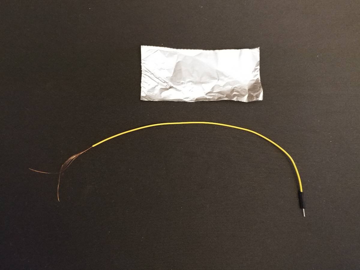
I used two project wires. I clipped one end. |
Strip the ends. Make sure you don't rip the wire like I did on the blue one! |
Cut a small piece of foil. |
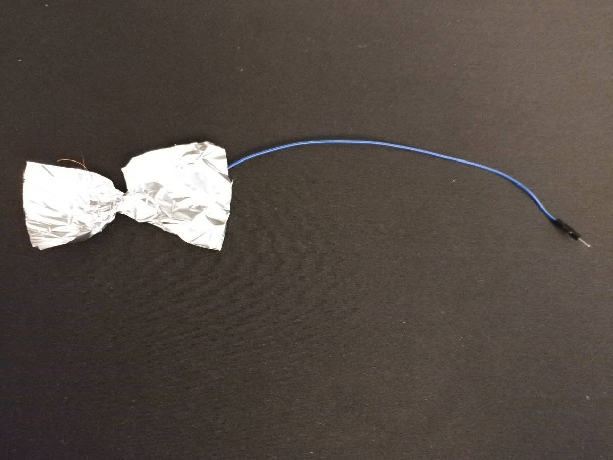
Twist the foil into a bow tie shape. Then wrap the wire around the center, twist more of the foil. |
Fold over the foil. It's not perfect, but it works. |


STEP 5
Setup:
Plug USB 5V power to the Micro:bit.
Do not touch the pads (electrodes)
At this point, the system will start and you should see some LEDs lit. Wait a few seconds for the LEDs to become stable. What’s happening is that the voltage is being sensed between ground and the pot+10k resistor in reference to VCC (3.3V in this case).
- Short the pads/electrodes. Wait, and the LEDs will go down to one. IT WORKS! Now we have to calibrate it.
- Separate the two pads. Don’t touch them. Wait for a stable signal on lines 1&2, aka the progress bar.
Adjust the potentiometer until there are around 8 LEDs lit up on the progress bar (lines 1&2).
Then you should see the lower 3 lines lit up about half. Press button “A.”
This sets the current average reading to be about center.
- Be in a calm state, and touch the two pads with your fingers. Press the “B” button.
This button will set the span to show the max and min on the progress bar since the last button “A” press.


After setting the system, I touch it and the bottom three lines almost disappear. I must have been nervous. 
- Now find someone you want to test compatibility with. Hold their hand, and both of you touch a pad. The less LEDs on in the bottom 3 lines, the “more compatible you are.”
- Alternatively, you can either test your stress levels after doing something. You should see a difference since the last time you touched the pads.
Conclusion:
This project isn’t as cutsie as the Hana Yori Dango Inspee, but it’s the basis for a similar device.
I could, technically, refine the code and output to 6 LEDs and stuff it in a 3D printed Inspee… but that’ll have to be a project for another time.
Now go forth and test some compatibility!