


MATLAB is technical computing software and also a high level programming language which can be used for visualizing data. In conjunction with Simulink, the MATLAB platform can be used for simulating dynamic systems found in nature and industry. All of this was new to me so I figured the first step would be to take the online tutorial "MATLAB Onramp." 
I got through about 35 percent of this online learning course before my attention started to wane. There are only so many ways I'm interested in programming an array and then accessing data within it. None of this would be important for me when programming robots under the time constraints of the Educator's Road Test. In the end, I prefer learning by doing so I decided to jump right into the world of technical computing without hesitation (and trust me, neither should you  )....
)....
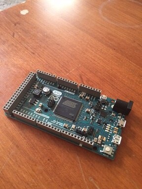
Above is my chosen stallion of a microcontroller to be used in conjunction with Matlab and Simulink; the Arduino Due gifted by element14.com. From my research I learned that the benefit of using an Arduino Due over an Uno is the faster processing power which can be helpful when negotiating data from multiple sensors. I would later learn that the most interesting capabilities of Simulink are not functional on an UNO therefore the Arduino Due is the "fete du joure" for my robot's brain!
My educator's road test packet also included a TMP36 Temperature sensor. This sensor is something that I have used in the past and for learning the following Adafruit tutorial was helpful:
https://learn.adafruit.com/tmp36-temperature-sensor/using-a-temp-sensor
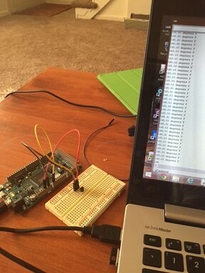
Past this code into an Arduino IDE to test the sensor; serial values for Fahrenheit will stream into your mind like the matrix:
//TMP36 Pin Variables
int sensorPin = 0; //the analog pin the TMP36's Vout (sense) pin is connected to
                        //the resolution is 10 mV / degree centigrade with a
                        //500 mV offset to allow for negative temperatures

/*
* setup() - this function runs once when you turn your Arduino on
* We initialize the serial connection with the computer
*/
void setup()
{
  Serial.begin(9600);  //Start the serial connection with the computer
                      //to view the result open the serial monitor
}

void loop()                    // run over and over again
{
//getting the voltage reading from the temperature sensor
int reading = analogRead(sensorPin);

// converting that reading to voltage, for 3.3v arduino use 3.3
float voltage = reading * 5.0;
voltage /= 1024.0;


// now print out the temperature
float temperatureC = (voltage - 0.5) * 100 ;  //converting from 10 mv per degree wit 500 mV offset
                                              //to degrees ((voltage - 500mV) times 100)

// now convert to Fahrenheit
float temperatureF = (temperatureC * 9.0 / 5.0) + 32.0;
Serial.print(temperatureF); Serial.println(" degrees F");

delay(1000);                                    //waiting a second
}
Comfortable knowing that the temperature sensor was working it time to explore how to incorporate Arduino hardware with MATLAB.
What is nice about MATLAB are the support packages which can be downloaded conveniently from a tab in the MATLAB integrated development environment. For the purpose of the educator's road test Madhu Govindarajan (from MATLAB and the element14 community) created a great blog on how to access these online support packages and then get temperature reading from the TMP36 sensor in MATLAB. Marvel at his work!
The first step was to download the support packages for MATLAB and Simulink (I'd need Simulink later). This downloading processes was very slow, and in fact, booting up MATLAB each time feels like an eternity and was very boring. I found myself playing Geometry Dash and chess on my iPhone to pass the time.
After the support packages were downloaded, I downloaded the files found in Mathu's blog in MATLAB and then a big bada-bing! Per run of this script a temperature reading would appear in MATLAB. How special, and this was a good start but nothing fantastic. What I really wanted was a deeper understanding of how to use MATLAB so I perused the community page which can be accessed from the interface:
Through my research I learned how to declare an Arduino object in the MATLAB command line as follows:
a = arduino('com8', 'due');
And then a simple way to elicit a digital write to an Arduino object as follows:
writeDigitalPin(a, 'D11', 1);
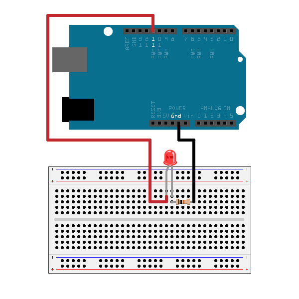
Like I said before, MATLAB is it's own programming language by itself. For the above code, the wiring would look like this (the picture is of an Arduino Uno (not Due) but you still get the idea)
Now I wanted to produce some dynamic visualizations. Specifically, I wanted to graph the readings from my TMP36 so they appeared in a graph over time and as the readings were taken! To figure out how to do this I needed to adapt Mathu's temperature reading scripts (which would only give one reading per execution of the code) into something which records multiple values over time and then graphs as it goes. I'd need to bulk up my knowledge of MATLAB syntax and I found thisyoutube.com tutorial to help me out:
The MATLAB script I crafted is a hybrid of this video and the scripts that Mathu wrote. Here it is, and the sensor was attached to pin 'A7' :
a = arduino('com8','due');
tic;
i=0;
while toc <25
    i = i +1;
    time(i) = toc;
    voltage(i) = readVoltage(a,'A7');


    tempinCel = (voltage*100) - 50;
    tempinFa = (tempinCel*1.8) + 32;

    figure(1);
    plot(time,tempinFa,'r');
    pause(.25);
end
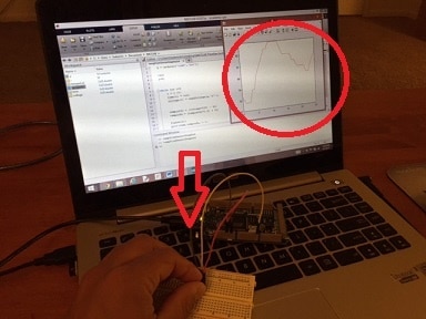
The video here shows me running the code::
A cool feature in MATLAB is once you have a series of data points; as what I collected with my temperature sensor over time; you can visualize the same data in multiple ways with the click of the button. For example, the graph shown in the video could be turned into these trendy visualizations by selecting the "Plots" toolbar at the top of the interface:

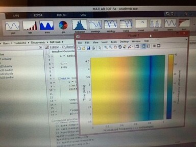
I'll admit that the visualization on the right doesn't mean anything to me but maybe it would at the Guggenheim.
SIMULINK
Simulink is a graphical programming language used for visualizing dynamic systems and it can also be used as a type of control interface for hardware. Simulink has industrial uses for simulating the flow of components in some very some serious machinery: Think Boeing Jets and car cooling systems......these are the types of grand endevors Simulink can model....
But when I began to use Simulink with an Arduino Due the hardware simply wasn't working; even though I downloaded the appropriate support packages and referenced this page for my first snippet of code:
Getting Started with Arduino Hardware - MATLAB & Simulink Example
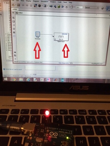
Simulink works by dragging and connecting blocks representing code. It's like SCRATCH programming but with some serious math incorporated into some of the blocks.In the end, all I was trying to get an LED to blink by connecting two measly blocks, as described here:

Okay, sounds easy, but then I got the following error every time I tried to execute the code on the "Due":

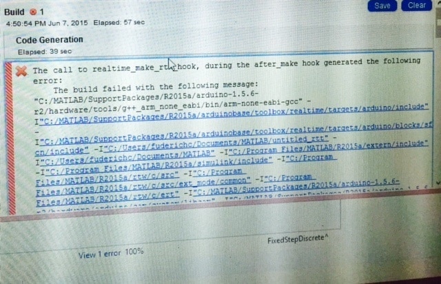
These Simulink blocks did work with an Arduino Uno though:
Confusing....
Using the Arduino Uno for my robotics project was not an option because I am dedicated to making use of the Simulink's ability to run a script in "external" mode which means you can adapt the code as it is running on the Arduino. Understand it like this: if you load up the script for a blinking function onto an Arduino but you can change the Simulink block for Pulse Width Modulation while the code is in the process of running and this will be outputted dynamically onto the hardware. This amazing function is not supported on the plebeian Arduino Uno.....
Eventually, I contacted Mathu and he was kind enough to offer me help in getting my Arduino Due to work. The solution was to change some of the file paths used to support Arduino hardware in MATLAB. Also, he sent me two new files to replace ones already existing within the supporting hardware paths and this was the action which really resolved things. If anyone has experienced these errors or is experiencing these errors when using a Due with MATLAB please contact me. I'd be interested in hearing how you figured things out.
Once resolved: The external mode in MATLAB allowed me to take my programming experience to a new level:
Light up Switch/ Control Interface:
Here is a video of me running a Simulink code where I can click the "Switch" button to turn a LED light on and off...
YOU CAN DOWNLOAD MY SIMULINK CODE: HERE
Dynamic systems: Visualizing Celsius and Fahrenheit

This was really fun and I'll admit that my Simulink code is probably not "elegant" and streamlined because I haven't figured out how to use the function block yet. Regardless, I did manage to get the sensor to read both Fahrenheit and Celsius in display tabs and this feels like an accomplishment:
You can download this Simulink code HERE!
In conclusion, I am very impressed with Simulink and MATLAB but the software engineers need to iron out the Arduino support package so you can run scripts without error (and stress). I honestly wasted days trying to figure out what was wrong before contacting Mathu for help.
When Simulink is working though, the software is great because it allows you to focus on the modeling process rather than writing low level code. Specifically, Simulink has libraries which allow you to not have to declare variables and structure code in a way a typical Arduino compiler needs; this saves time and makes things easier for beginners. Also, the fact that you can run scripts in external mode and change the functions of code "on the fly" is innovative and really helpful for tweaking hardware. In the end, you've got so many different mathematical blocks and interesting visualizations to choose from with Simulink and MATLAB and this can really make your simulation "dazzle."
In my next blog, I am going to use Simulink to program my Parallax Robot- "Tara-bot".

