Would you like to see this IoT proposal developed further? Head over to our University IoT Challenge voting page to help this project get turned into a reality.
Modern agriculture applications necessitate cheap, low-maintenance and low-cost wireless telemetry for various environmental parameters, such as environmental humidity, soil moisture, barometric pressure, and temperature. Continuous and dense environmental monitoring is critical for optimal crop and water management techniques and thus, wireless sensor networks (WSN) for microclimate monitoring in extended areas, are indispensable within this topic. One important environmental variable that needs careful monitoring, especially in agriculture and water management applications, is percentage soil moisture. Leaf sensors is another way to measure the water status of the plants. With leaf sensors, more accurate results can be achieved thus the water measurements are taken from the plant itself and not into the soil or into the atmosphere. The monitoring of the water deficit stress (WDS) of the plans is based on temperature difference between the leaf and the air (Tleaf - Tair). This difference is strictly related to the plant water stress and can be used as decision parameter in a local irrigation system.
Conventional WSNs consist of a network of nodes (possibly in a mesh architecture), transferring monitored environmental data to a base station. Each node typically employs a Marconi type radio, controlled by a microcontroller unit (MCU) and the sensors. However, large-scale deployments of conventional WSN technology are uncommon, due to power consumption, installation, and maintenance cost. In order to address power consumption and cost per sensor constraints, backscatter radio has attracted interest the last years for wireless sensing development. Using backscatter radio communication, the front end of each sensor node is simplified to a reflector (an antenna connected with a transistor) that modulates information on the sensor’s antenna-load reflection coefficient. With this concept, communication is performed by means of reflection, where signal conditioning such as filtering, mixing or amplification at the sensor/tag are typically avoided; in that way, low power consumption is needed, offering opportunities for battery-less operation. So, backscatter radio communication is a method that solves those limitations by reflecting and modulating an incident radio frequency (RF) carrier. It is used in radio frequency identification (RFIDs) applications and offers ultra-low power and low-cost aspects. In a backscatter WSN, each sensor is battery-less and can be powered using ambient radio frequency (RF) energy with appropriate rectifiers or using multiple kinds of ambient energy sources, such as RF and solar energy, simultaneously.
This proposal discusses the implementation of 30 low cost and ultra-low power wireless sensor nodes/tags for agriculture based on backscatter principles. The tags will be connected with soil moisture and temperature leaf sensors for water deficit stress (WDS) measurements outdoors and will reflect RF signals from a carrier emitter. Each sensor will be a part of a big backscatter WSN and it will transmit the data to a low-cost reader. Each tag consists of a microcontroller (MCU) and an RF front-end for the backscatter communication. There is also a sensor board for the measurements and a circuit for the power supply. The tag reads the information from the sensors and generates pulses that control an RF switch (or transistor). The low complexity OOK modulation technique was selected for the backscatter modulation and each tag sends the measurements to a low-cost software-defined radio (SDR) reader.
The WSN employs semi-passive (energy assisted) tags in monostatic topology thus the reader is in the same box with the carrier emitter. The 868 MHz in the European RFID band, was selected as carrier emitter frequency. Every novel proof-of-consent prototype is battery-less and was powered by a small solar panel consuming power around 20 uW. Finally, has been already demonstrated wireless operation indoors up to 10 m distance for one only proof-of-consept prototype. Preliminary results on these sensors nodes on backscater tags were proposed in our previous research work:
http://daskalakispiros.com/files/daskalakis_mtt_2015.pdf
http://daskalakispiros.com/files/2017_sensors_daskalakis.pdf
http://daskalakispiros.com/files/daskalakis_mtt_2017.pdf
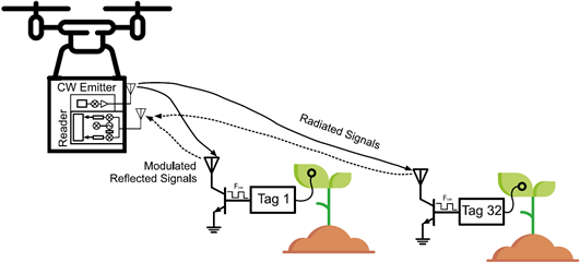
Direct sensing can make agricultural systems safer, more efficient, more accurate, and more productive. However, agricultural applications frequently involve large, expansive areas where wireless connection for communication and power is undesirable or impracticable. For the above reason is proposed the above low-cost, battery-free backscatter WSN with a reader/emitter box installed on a hexacopter unmanned aerial vehicle (UAV-drone). The concept is depicted in below Fig. 1. The drone will carry a battery-powered RFID reader with data logging capabilities for easy access and communication with the sensors. The drone will fly to the designated field area (vineyard for example) and retrieve the information wirelessly from the RFID based sensors. Once the flight is finished and the drone is near to the base station (home), the reader system will upload the information to the cloud via a WiFi link.
Fig. 1
BACKSCATTER COMMUNICATION
A typical backscatter communication system requires three devices: a sensor node/tag, an emitter, and a reader. Traditional batteryless RFID systems utilize monostatic architectures thus the reader is in the same box with the carrier emitter (Fig. 2). The emitter sends a carrier wave (CW) signal which is a 868 MHz cosine in our case. The tag receives this signal and scatters a fraction of it back to the reader. The backscatter binary communication on the tag can be implemented with an RF switch (or transistor), an antenna, and a control unit (MCU).
Fig. 2
SENSOR NODE/TAG
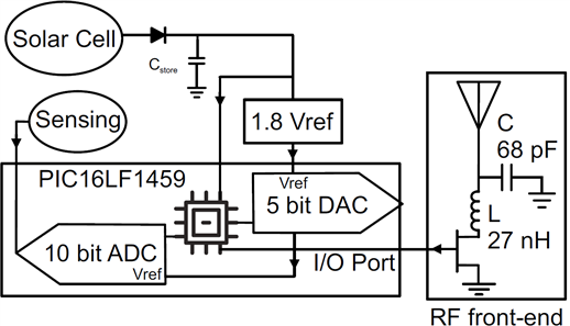
The proof-of-concept tag consists of three different parts. These parts are the MCU unit, the sensor board, and finally RF front-end. The MCU unit is the main part of the system and it is responsible for the data sensor acquisition, the implementation of the modulation symbols and the control of the other parts. The schematic of the main system is depicted in Fig. 3. The ultra-low power 8-bit PIC16LF1459 from Microchip with current consumption only 25 uA/MHz at 1.8 V was selected for the MCU. The MCU collects data from the sensor board using the embedded analog-to-digital converter (ADC) with 10-bit resolution. The internal 31 kHz low-power oscillator was utilized as the clock source to reduce the power consumption of the tag. The MCU is responsible to supply all the other parts with voltage when it is necessary. In sleep mode, the MCU current consumption was only 0.6 uA at 1.8 V. The MCU was supplied by a low power voltage reference integrated circuit (IC) at 1.8 V (XC6504) the XC6504 provides also stable reference voltage at the ADC. A small solar panel is used to charge a capacitor with acts as an energy tank. The MCU generates 50% duty cycle pulses that control the RF switch, thus generating an OOK modulated backscattered signal.
Fig. 3
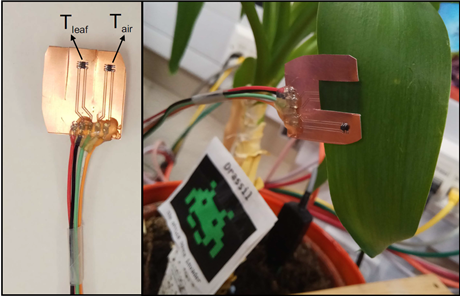
Two different sensor boards will be fabricated for our tags, one for leaf sensing and one for soil moisture. The soil moisture sensor is a capacitive sensor consisted of two isolated conductive plates, separated by a narrow gap, on a low-cost FR-4 substrate; waterproofness will be facilitated using the solder mask as insulation. The leaf sensor board consists of two analog temperature sensors LMT84 by Texas Instruments. Each sensor is connected with an ADC input and consumes 5.4 uA at 1.8 V. The accuracy of each one is: +-0.4C and both were placed on a “clip” scheme board to be easily fixed on a leaf. A proof-of-concept prototype placed on a leaf as it is depicted in the delow figure.
Fig. 4
The RF front-end part consists of an RF switch (or transistor) and a custom dipole antenna (Fig. 2). The RF front-end is connected with an I/O pin of the MCU (Fig. 4, bottom) and is necessary for the wireless communication with the reader. It is responsible for manipulating the reflections of the incident CW signal. The single-pole-double-throw (SPDT) switch ADG919 was selected due to its low insertion loss and high “OFF” isolation. The “RFC” and the “RF2” terminals of the RF switch were connected with the two elements of the dipole antenna. The dipole antenna has omnidirectional attributes and was designed for operation at 868 MHz. An RF front-end prototype has been fabricated using copper tape on cardboard substrate. The bottom picture in Fig. 4 offers the fabricated circuit and the dimensions of the antenna.
Fig. 4
In our tag, a solar panel will charge a super capacitor instead of a battery through a low voltage drop Schottky diode. For the diode, the SMS7630-079LF by Skyworks Inc. with forward voltage drop only 150 mV has been selected. On the tag, a real-time algorithm has been implemented in order to read the sensor information and send them wirelessly at the receiver. Subsequently, an interrupt signal coming from the reader is used to wake up the MCU. Firstly, initialization of the system (ADC, clock, I/O pins) is achieved and the ADC is enabled for data capture. The two temperature sensors are consecutively powered and the ADC reads the data from each one. The ADC is turned off immediately after this action for reducing the energy consumption. The tag was programmed to send a packet of information with fixed format every time the algorithm is running.
READER & EMITTER
In our system, the temperature or the soil moisture ADC data are received by a low-cost SDR. This receiver is the “NESDR SMArt” SDR available by the NooElec (Fig. 4, top). It is an improved version of classic RTL SDR dongle based on the same RTL2832U demodulator with USB interface and R820T2 tuner. The USB dongle can be easily installed on a Raspberry Pi 3 single-board Linux computer. The Raspberry Pi 3 has enough processing power run the receiver algorithm easily with the RTL-SDR. For the emitter, a Silicon Laboratories SI1064 ultra-low power micro-controller unit (MCU) with integrated transceiver was configured to transmit a sine/cosine wave at UHF frequency 868 MHz, with a transmission power of 13 dBm. The SI1064 can be used alternatively for the reader instead of the RTL-SDR but it is required more time for research and implementation.
We will employ a commercially-available hexacopter (Tarot 680PRO) as our unmanned aerial vehicle (UAV). The Tarot 680PRO has classic hexacopter frame, 695 mm motor to motor with foldable arms and legs, compatible with a 13" propeller. Featuring a carbon bottom frame and PCB top frame, we could solder the electronic speed controller power cables directly onto this PCB top frame and avoid a lot of messy cabling. The adjustable battery mount (LiPo pack) will allow us to balance the drone with a best center of gravity (C.G.), thus we plan to put the transmitter and the reader on the drone. Also the transmitter, the reader and the Raspberry Pi board will be powered by the same LiPo battery. Due to its simplicity, it's a reliable and compact hexacopter platform which can gives us about 1.5-2.5 kg of payload capacity. The drone will remain in the line of sight with all the sensors during the scanning and will also feature an emergency human override via to its separate 2.4 GHz manual radio remote control (RC). Patch antennas for the reader and emitter will be mounted on the drone in a downward fashion to read tags one by one as the vehicle will hover nearby with a maximum height 10-15 m.
DRONE GROUND CONTROL & VISUALISATION
The proof-of-concept tags will be measured outdoors with the transmitter the reader installed on a unmanned aerial vehicle (drone) in order to validate the effectiveness of our backscatter communication system. The emitter, the tag and the reader will tested in monostatic architecture thus the two part will be in the same box on the UAV. Using the autonomous vehicle, we will develop a series of simple robot behaviors to read the RFID tags. These behaviors are based on a few high-level action primitives: navigate to GPS coordinate, circle around specific GPS coordinates, change altitude, takeoff or land. The combination of actions resulted in robot behaviours to detect tags and obtain sensor measurements. For control station (GCS) software, the open-source ground station application APM Planner 2.0 will be used in combination with a database and MATLAB for sensor visualization. The software will collaborate with a Pixhawk 2 Autopilot hardware on the drone. Using APM Planner GUI, the farmer could indicate a series of waypoints (candidate tag locations) or an area for the UAV autonomous search/scanning.
BILL OF MATERIALS
In order to manufacture the proposed WSN with the drone reader, specific parts, components are needed. The list of the components for 30 tags and the drone reader is attached below via a dropbox link.
https://www.dropbox.com/s/c1bqfgwo31ltu3m/RS.xlsx?dl=0 Also a more detailed report is attached


Top Comments
-

stevaras
-
Cancel
-
Vote Up
+1
Vote Down
-
-
Sign in to reply
-
More
-
Cancel
Comment-

stevaras
-
Cancel
-
Vote Up
+1
Vote Down
-
-
Sign in to reply
-
More
-
Cancel
Children