

Introduction
Electromechanical relays employ movable contacts to control high voltage devices such as motor controllers and temperature controllers from a trigger voltage. In terms of operation, Solid State Relays (SSRs) are not very different from electromechanical relays, but they do not have movable contacts; rather, they employ semiconductor switching elements, such as thyristors, triacs, transistors, and more. MOSFET relays are a subset of the class of solid state relays (SSRs), using MOSFETs to drive their output loads. They are mainly used for switching and connecting signals, especially for the precise control (with low distortion) of small analog signals. This article will cover MOSFET relays, including a solid state relay overiew, MOSFET relay operation, benefits, and best practices of working with them.
Overview of Solid State Relays
A typical solid state relay is designed as an on-off switch with a low power input terminal and a high power drive output terminal. Figure 1 indicates the internal diagram of a typical SSR.
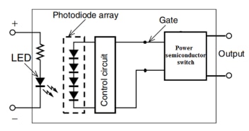
Figure 1: Internal diagram of a typical Solid State Relay
The SSR is constructed using a light emitting diode (LED), photodiode dome array (PDA), a control circuit, and one or more semiconductor switches. A series resistor is used to limit the input current. The low voltage input drives an LED to generate a light source which is further detected by the PDA. The combination of LED and PDA provides optical-isolation and helps to transfer the input signal to the gate control circuit. Semiconductor switches such as SCRs, TRIACs, bipolar transistors are used to drive the flow of source current to the load. SSRs support both AC and DC waveforms, but the internal configuration has to be modified to work for either scenario.
Figure 2 shows a TRIAC-based AC-operated relay circuit diagram. In this example, an in-built input circuit is used to limit the forward dropout voltage for the LED.
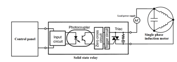
Figure 2: Diagram of AC operated TRIAC-based relay circuit
The zero crossing detection circuit is used to take the reference of positive and negative cycles of the AC voltage. The control panel provides an input signal to the terminals of the solid state relay. Using that signal, the triggering circuit generates the gate plus for the TRIAC. During on-time, the TRIAC allows the AC voltage to the load (induction motor). A Resistor-Capacitor (RC) snubber network is required across the output terminals to protect the semiconductor device from noise and voltage transient spikes.
SSRs are well suited for industrial applications such as solenoid controlled valves, temperature controllers, motor controllers, and lamps. Figure 3 shows a block diagram of a DC motor controller where an SSR acts as a DC motor drive to control a solenoid or an electromechanical valve. The Programmable Logic Controller (PLC) provides the control signal to the SSR to operate the DC motor. The DC motor usually creates back EMF (electromotive force). If the electromotive force exceeds the withstand voltage of the SSR output element, it could result in damage to the relay output element. To prevent this, connect a freewheeling diode (Df) in parallel with the DC motor.
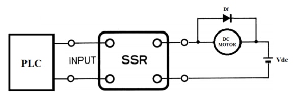
Figure 3: DC motor controller
Introduction to MOSFET Relays
A MOSFET relay takes a low power electrical signal to turn on or off the high power electric signal through the load. Figure 4 illustrates the operation of a MOSFET relay. MOSFET relays are SSRs that use power MOSFETs in their output elements. In order to operate the power MOSFETs, photodiode arrays are used as light-receiving elements. When current flows into the input terminal, the LED lights. This light generates a photoelectromotive force in the photodiode array, and this acts as a gate voltage that turns ON the power MOSFET. By connecting two power MOSFETs using a source common, control of AC loads is possible. There are models for control of DC loads, which have just one power MOSFET. MOSFET relays can be utilized for AC and DC applications:
- AC Switching: Figure 4 shows the two MOSFETs (S1 and S2) are connected back to back with two inherent substrate diode (D1 and D2). In a AC conduction mode, the upper MOSFET (S1) and Diode D2 allows the positive cycle to the load. Similarly, during the negative cycle diode D1 and lower MOSFET (D2) allows the negative cycle.
- DC Switching: A DC switching relay has a single MOSFET, or multiple MOSFETs arranged in a paralleled array. The MOSFETs in the DC switching relay operates in accordance with the control signal.
Benefits of MOSFET Relays
MOSFET Relays have a number of benefits. Let's discuss the main ones in this section:
- Ultra-small and lightweight: SOP, USOP and other new ultra-small packaging VSON are emerging, which contributes to miniaturization of the entire device.
- Low drive current and power consumption: The drive current is about 2 to 15mA under normal operating conditions. Some MOSFET relays have a minimum of 0.2 mA, which contribute to energy saving of whole device. The typical power consumption of a MOSFET relay is ~3mW.
- Longer-life: MOSFET relays have a non-contact structure using an optical signal transmission method, which allows for a high level durability and a very long life as compared to electromechanical relays.
- Small leakage current: Because of its high resistance to external surges and no added snubber circuit, the leakage current is extremely small, typically 1 nA or less in the off state.
- Superior impact resistance: Since the internal parts are completely molded and there are no mechanical parts, they have excellent shock and vibration resistance.
- Quiet Operation: Since there is no switching noise caused by metal contacts of electromechanical relays, MOSFET relays operation with very low noise.
- High insulation: They have high dielectric strength due to their opto-isolated input circuit.
- Precise control of small analog signals: Compared to a triac, the MOSFET greatly reduces the dead zone, so the input waveform of a small analog signal is converted into an output waveform with little distortion.
Working with MOSFET Relays
Do not apply overvoltages or overcurrents to the input or output circuit of the MOSFET Relay. The MOSFET Relay may fail or ignite. Perform soldering and wiring correctly according to specified soldering conditions. Using a MOSFET Relay with incomplete soldering may cause overheating when power is applied, possibly resulting in burning.
To use a MOSFET Relay with high reliability, consider derating the maximum ratings and recommended operating conditions, and allow sufficient leeway in designs based on testing operation in the actual application under the actual operating conditions whenever possible.
The maximum ratings must never be exceeded even instantaneously. This applies individually to each of the ratings. If any of the maximum ratings is exceeded, the internal parts of the MOSFET Relay may deteriorate or the chip may be destroyed. To ensure high reliability in using a MOSFET Relay, sufficiently derate the maximum voltage, current, and temperature ratings when designing the application.
The recommended operating conditions are to ensure that the MOSFET Relay turns ON and OFF reliably. To ensure high reliability in using a MOSFET Relay, consider the recommended operating conditions when you design the application. Perform solder mounting under the following recommended conditions to prevent the temperature of the MOSFET Relays from rising.
Implement fail-safe measures in the design of the application if the failure of, deterioration of characteristics, or functional errors in the MOSFET Relay will have a serious effect on the safe operation of the system.
There is a risk of damage to internal elements and impairment of functionality if static electricity is discharged to the pins due to product handling or otherwise. Reduce the generation of static electricity as much as possible, and implement appropriate measures to prevent charge accumulation near the product.
Clean flux from the MOSFET Relay so that there will be no residue of reactive ions, such as sodium or chlorine. Some organic solvents will react with water to produce hydrogen chloride or other corrosive gases, which may cause deterioration of the MOSFET Relays.
Store the MOSFET Relay where they will not be subjected to water leaks or direct sunlight. When transporting or storing the MOSFET Relays, observe all precautions on the packaging boxes. Keep the storage location at normal temperature, normal humidity, and normal pressure.
Do not store the MOSFET Relay in locations that are subject to corrosive gases, such as hydrogen sulfide gas, or to salt spray, and do not store them where there is visually apparent dust or dirt. Store the MOSFET Relay in a location that has a relatively stable temperature. Radical changes in temperature during storage will cause condensation, which may oxidize or corrode the leads and interfere with solder wetting.
MOSFET Relay Driving Circuits
Refer to Figure 4. The LED input side of the MOSFET is driven by current. When applying a voltage, add resistance in series with the circuit, so the specified current is applied. This resistance is referred as "LED current limiting resistance".
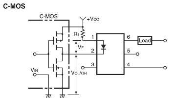
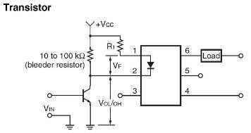
Figure4: Typical MOSFET Relay Driving Circuits
To ensure that the MOSFET relay operates correctly, use the following formula to calculate the limiting resistance, and design the circuit accordingly.
Protection from Spike Voltage on the Output Pins of the MOSFET Relay
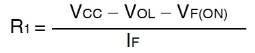
If there is an inductive load or other condition that will cause an overvoltage that exceeds the absolute maximum rating between the output pins, connect a protective circuit to limit the overvoltage as diagrammed in Figure 5.
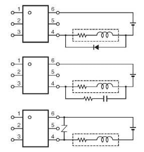
Figure 5: Spike Voltage Protection Circuit
Protection from Surge Voltage on the Input Pins of the MOSFET Relay
If any reversed surge voltage is imposed on the input pins, insert a diode in parallel with the input pins as shown in Figure 6. Do not impose a reversed voltage of 3 V or higher.
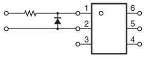
Figure 6: Surge Voltage Protection Circuit
Load Connection Examples of a MOSFET Relay
.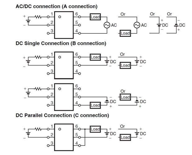
Figure 7: Example of correct connection
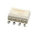
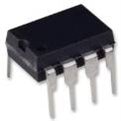
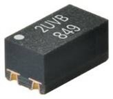
Examples of MOSFET Relays
| MOSFET RELAY, SPST-NO | MOSFET RELAY, SPST-NO | MOSFET RELAY, SPST-NO | MOSFET RELAY, SPDT |
|---|---|---|---|
G3VM-201FR (TR05) For More InformationFor More Information |
G3VM-61cr1 For More InformationFor More Information |
G3VM-21UV11(TR05) For More InformationFor More Information |
G3VM66M Product LinkProduct Link |
Top Comments
-

clem57
-
Cancel
-
Vote Up
+1
Vote Down
-
-
Sign in to reply
-
More
-
Cancel
Comment-

clem57
-
Cancel
-
Vote Up
+1
Vote Down
-
-
Sign in to reply
-
More
-
Cancel
Children