


This blog was sparked off (in part) by airbornesurfer’s January blog about renovating his Califone 1430k school record player,
I suggested that rather than use a nasty modern switching amplifier he should build a nice period-correct transistor amplifier.
This got me thinking ……..
The first successful (it worked, I got paid) commercial electronic project I ever did was in about 1971 when I built a 25W Mullard designed power amplifier. It was to be used as a guitar practice amplifier.
Mullard was one of the early electronics companies, and as was common in the 60s and 70s published a good range of designs to promote the parts they made. In 1969 they published a small hardback book “Transistor Audio and Radio Circuits.”. It contains many gems and one of them is the 25W Audio Amplifier.
The design was typical of the period and unlike later designs substituted capacitors for transistors. The staggeringly successful Quad 303 power amplifier used a similar (but more sophisticated and better performing design.)
For a good description of a contemporary and much lest cost inhibited design look up “Barney Oliver Amplifier” – this was an HP home time project from 1973.
Most of the semiconductors in the original Mullard design are obsolete – so my re-working of it uses parts that are current and available.
The book is available as a pdf on the web.
My revised design:

I’m going to keep this blog reasonably brief so I won’t describe in detail how it works (and the Mullard book doesn’t either) – but later I mean to see how much better we can do – and that will mean getting into the guts of the design to see if we can improve it, and how a more modern design gets round some of the problems.
I missed out on the recent E14 prototyping project so I’m using this amp as an example of how I go about building and testing prototypes.
First of all you need the design – in this case it came from a book. Then we need to develop it to use the bits we can get. Then we design a board.
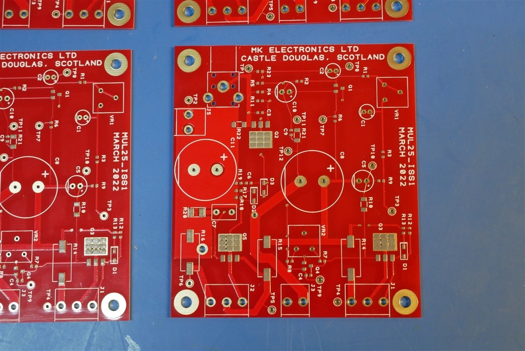
To design the board we have to start thinking about power and voltage ratings of components and I tripped up on this board with R9. The original design mislead me – it suggests that R10 should be rated at 500mW but makes no suggestion for R9. I did a quick calculation in my head - the steady state (DC) current though Q2 is about 5.7mA so the DC power in R9 is 15mW – so the 0603 resistor I used is fine. But there is a problem – C5 couples the output to the junction of R9 and R10 and we expect about 15V RMS on the output. At operating frequencies C5 impedance is negligible so at full output there is 15V RMS across R9, and that will make 479mW – too much for 0603. Although I’m not describing the circuit in detail – it’s worth mentioning that this trick of “bootstrapping” the drive to the output stage of power amplifiers was common at the time. More modern designs use extra semiconductors and replace R9 and R10 with a current source.
The other thing that went a bit wrong was the phono socket I used for the input – the drawing for this part isn’t very good and for it to work the centre pin needs an impossible slot in the pcb (4mm long and 0.5mm wide) – I had a round hole so the Dremmel came into play to improve the connector.
I buy my boards from PCBCART in China – reasonable prices and quick delivery. I go for gold plating because these prototype parts sometimes lie around for years and then find a new use. Immersion silver and solder levelled boards are usually too corroded to be readily soldered after a few months.
There has been some talk about powering up boards and I’ve managed to practice what I preach and get a reasonable number of test points on this one.
TP10 and TP3 will allow me to neatly fix the R9 problem by connecting a through hole part between them.
I rather like the 3W surface mount 0.47R resistors I found for this – they were on a cheapo at Farnell.
Boards after solder paste stencilling.
4 Boards ready on the hand operated pick and place
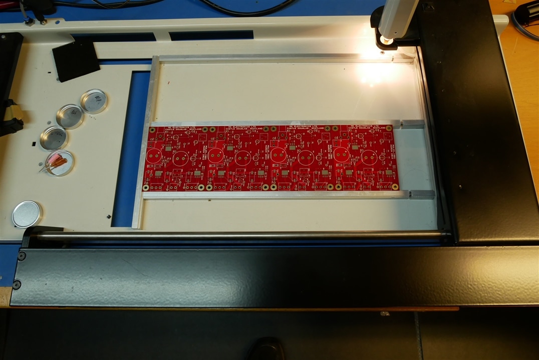
Ready to reflow

And with all the TH bits
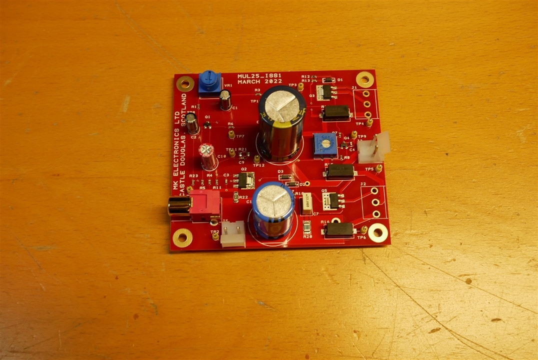
Finally, with power transistors and a heatsink – (there are insulators under the power devices)

Powering Up
I used a TTi QL564 linear regulated power supply.
I started up at 12V and 100mA – no problems. It starts to work when the supply gets over about 20V.
No nasty currents and no smell. The two pots worked OK. Supply up to 50V – current still nice and low (<10mA with VR2 set for minimum). I adjusted VR2 for about 40mA Iq and VR1 for 25V at TP5.
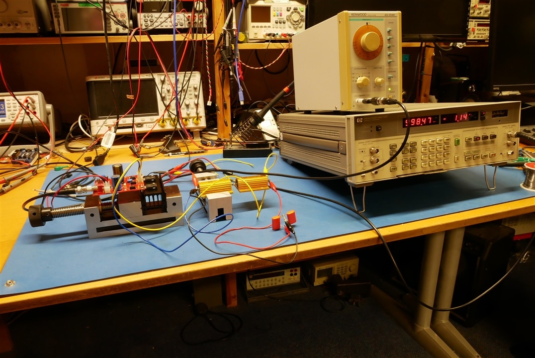
Then I ran it into a 47R load – using the HP8903A to look at output and to provide drive signals.
It was OK but the distortion was very high and the frequency response a bit odd.
Oh poo !
I had forgotten to fit R21 !
Everything much more sensible then.
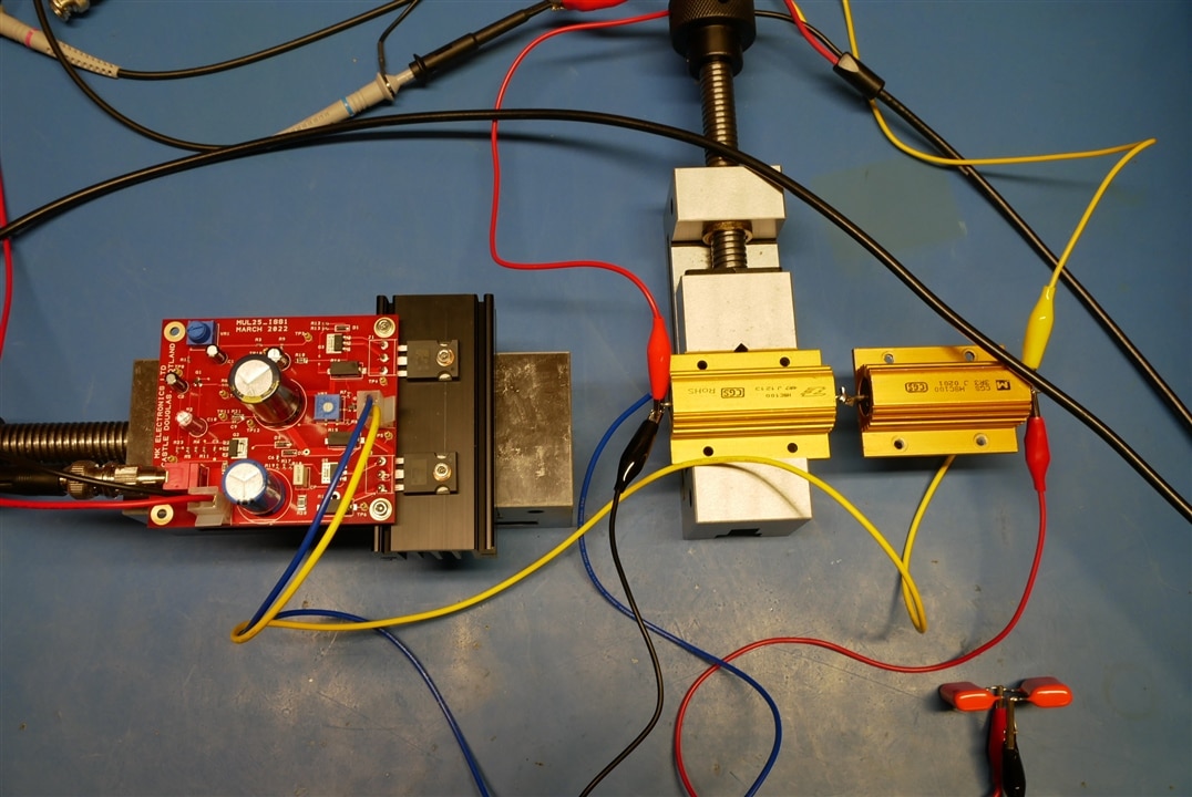
I did most of the initial testing with the QL564 power supply but switched over to a TTi MX180TP for the 4.7R load tests.
Testing
Amplifier and Load
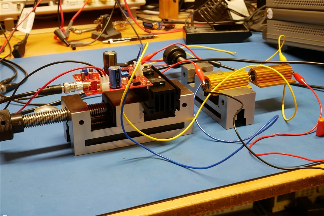
Test Setup
Capacitive Load Stability test
Gain 82.27 (expected 70.7 from Mullard book – I haven’t looked into the difference)
Input for full power into 8R load, 164mV
THD, 25W into 8R load, 50V supply HP8903B used for measurments:
50Hz 0.05%
1kHZ 0.08%
10kHz 0.69%
THD, 35W into 4R7 load, 50V supply HP8903B used for measurments:
1kHz 0.06%
THD at lower power 1kHz, 8R load
23mW 0.11%
93mW 0.07%
Wideband noise, measured with HP8903B output set to zero
0.4mV (signal to noise ratio full power to noise) = 91dB
Frequency Response, half power 8R load, ref 1kHz
20Hz -0.4dB
50Hz -0.02dB
10kHz -0.74dB
20kHz -2.24dB
30kHz -4.03dB
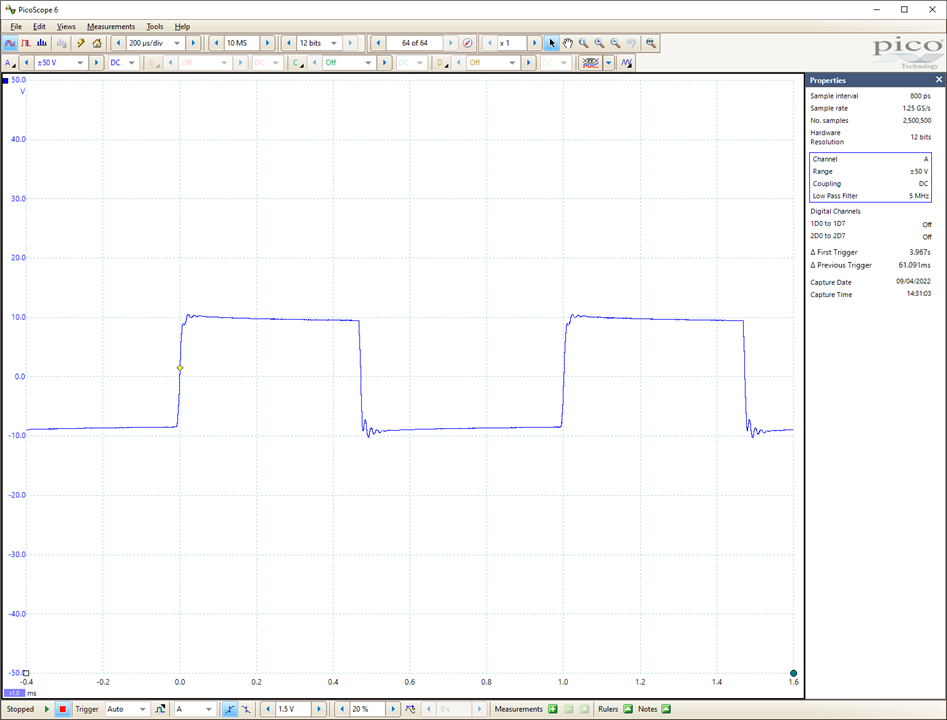
Stability, square wave drive 1kHz into 8R//2uF Kenwood AG-204D signal generator
Summary
The updated Mullard amp performs pretty much as the spec indicates. Its not up to modern HiFi standards but bearing in mind that the design is 50 years old that isn’t a surprise.
Hope this is useful to someone.
The next steps in this project for me are to finish developing the automated test system based on the HP8903A/B audio analysers.
I’ll also see if any simple tweaks can improve the amplifier.
If anyone fancies making their own I can supply Gerber files (or possibly even a board or two.)
MK
Top Comments
-

Jan Cumps
-
Cancel
-
Vote Up
0
Vote Down
-
-
Sign in to reply
-
More
-
Cancel
-

jc2048
in reply to Jan Cumps
-
Cancel
-
Vote Up
0
Vote Down
-
-
Sign in to reply
-
More
-
Cancel
Comment-

jc2048
in reply to Jan Cumps
-
Cancel
-
Vote Up
0
Vote Down
-
-
Sign in to reply
-
More
-
Cancel
Children