


A couple of weeks ago I posted my BD9G500EFJ-EVK-001 RoadTest review. It has been a fantastic experience, but I left untouched one very specific topic that I would like to cover: loop frequency response. I've never attempted a frequency response measure and I was determined to achieve it.
I had many missing pieces, namely I didn't have any viable way to generate a stimulus signal and furthermore it needs to be isolated from the mains ground to be injected into the BD9G500EFJ-EVK-001 feedback loop.
But it's Christmas time, so I decided to gift myself a very nice SDG2042X, and that solved the problem on the signal generator side 
Building an isolation transformer
This is a specialized piece of equipment and I can't really justify the expense for a commercial solution, so I decided to go on the "homemade" route. The goal is to obtain something that could work from a couple hundred Hz to maybe a couple MHz, with a minimum requirement of 100kHz. A lower maximum frequency is not going to cut it simply because the 0dB crossing frequency of modern DC/DC converters is in the 10kHz range and above. The BD9G500EFJ-EVK-001 I've modified and that I will test is probably going to have a crossover frequency around 50kHz.
My first test involved repurposing an old common mode choke recycled from a CRT TV many years ago. I breadboarded it but unfortunately it wasn't usable over 5kHz, so I had to find another solution.
Luckily, Maxim/Analog Devices has a really nice app note on this, AN3245, so I followed it and tried once again using, as they suggested, a current sense transformer as primary and a hand wound secondary with 8/9 turns.
This worked quite well, showing a nice flat response from 200Hz to over 1MHz. Under 200Hz the output waveform starts to be distorted, probably due to core saturation or other things I don't know
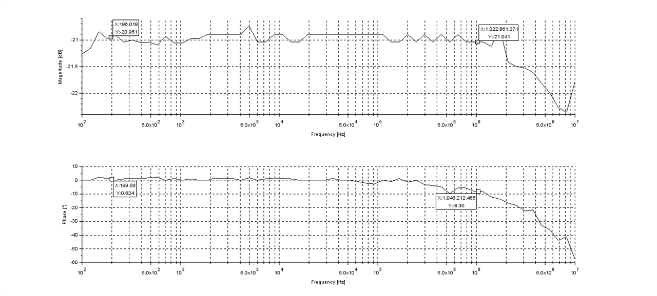 Isolation transformer frequency response
It worked so well that I decided to enclose it in a dedicated 3D printed case, to keep it as one of my instruments and tools!
| {gallery}Isolation transformer |
|---|
|
|
|
|
|
|


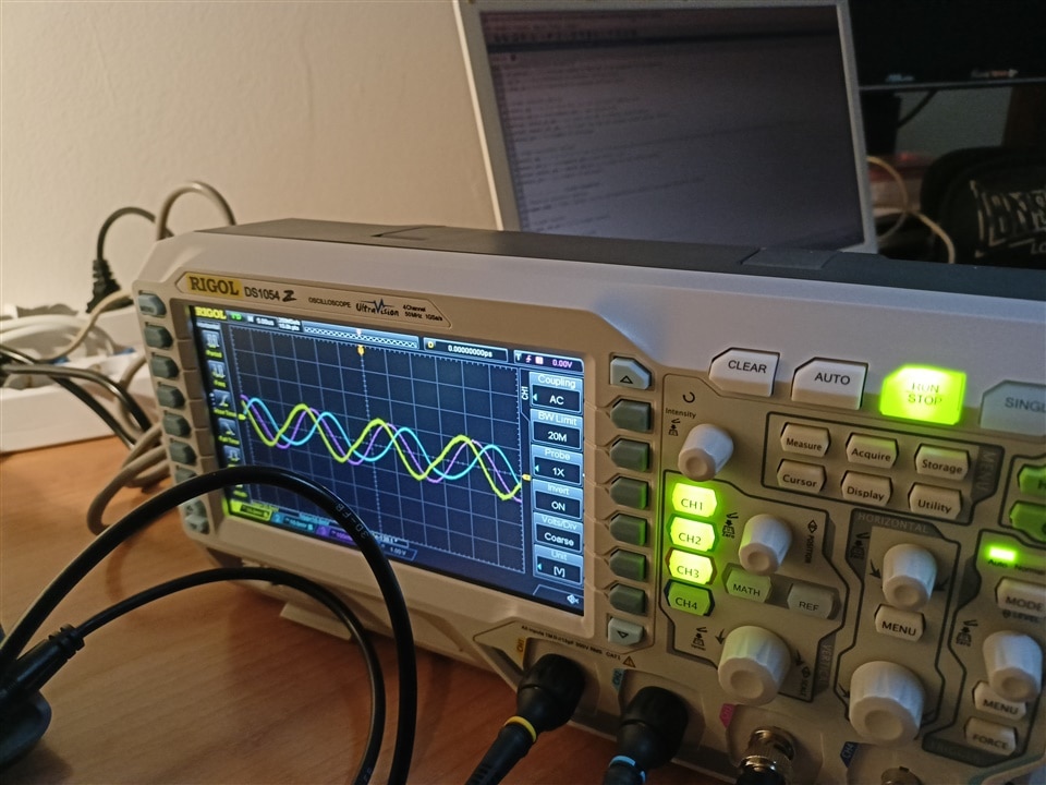
To coordinate both oscilloscope and function generator, I had to write a Scilab script. It's not the most clean piece of code I've ever written, but it works decently enough for me. It can scale automatically both channels to optimize dynamic range and after acquisition has ended it plots the obtained curve, ready to be saved.
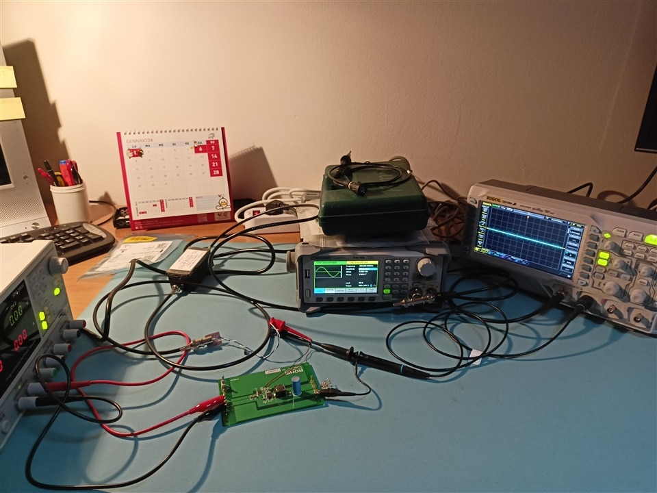
Setting up the measure
| {gallery}measure set up |
|---|
|
|
 |
 |
It took many attempts to get a decent result because I had to dial in many different parameters on both the stimulus signal (to avoid saturation and distortion) and on the acquisition side as well (to properly trigger on desired signal and reject noise). I also had to narrow the frequency span around the 0dB point and avoid measuring low frequency response. Luckily, it also happens to be the range I'm most interested in anyway .
| {gallery}loop frequency response |
|---|
|
|
|
|


The measure is pretty noisy but I'm glad it correlates well with the simulation. In fact the simulation gives me about 41kHz for zero crossing frequency and a phase margin around 53°, while I've measured a crossover frequency between 40kHz and 50kHz with a phase margin between 50° and 70°.
I will probably try to further optimize the acquisition step to reduce noise but for me this is a "mission accomplished"!
Scilab code (I had to change file format to .txt to upload it, to open with scilab change file format back to .sce):
/*NOTE:

    IMPORTANT: needs scilab 6.0.x to run! does not work on newer versions

    Program to control in conjunction a scope and a function
    generator to create a bode plot.

    Needs visa toolbox, use atomsInstall("visa") to install it
    If the toolbox does not start automatically, you have to load it manually!

    Setup done by script set up section

    IMPORTANT:
    Scope channels and acquisition mode (hires/average) need to be set up directly on the scope
	when using average mode, increase wait_meas_time accordingly

    Known ISSUES:
    -does not go under 100ns/div? in average mode, scope stops averaging...
*/

xdel(winsid());//note: xdel will be deprecated in future versions
clear;
clc;

disp("Script started");

//----------------------SCRIPT SET UP PARAMETERS------------------------------

//select between linear and log frequency sweep, plot will be affected as well
//choose one or the other
//sweep_type = "LIN";
sweep_type = "LOG";

//select between linear and log amplitude plot
//choose one or the other
//y_type = "LIN";
y_type = "LOG";

//start and stop frequency
f_start = 20000;
f_stop = 100000;

//number of points
sample_n = 40;

//delays (in milliseconds)
wait_meas_time = 3000;// default acq mode or Hires:1200
wait_set_time = 300;

//max number of measure attempts for each frequency point
max_measure_attempts = 4;

//----------------SCOPE PARAMETERS
//scope address
scope_addr = "USB0::0x1AB1::0x04CE::DS1ZA211403170::INSTR";//My scope address

//scope channels
scope_in_ch = "1";//dut input signal
scope_out_ch = "2";//dut output signal

//measurement decision parameters
n_of_period = 1.5;//minimum number of periods to be acquired for one measure
v_up_th = 0.95;//threshold to increase vertical scale
v_down_th = 0.35;//threshold to decrease vertical scale

//scope vertical options
vscale_opt = [0.01;0.02;0.05;0.1;0.2;0.5;1;2;5];//option list
vscale_opt_n = size(vscale_opt);//get vector size
actual_vscale_in_opt = 8;//index for the in channel actual option
actual_vscale_out_opt = 8;//index for the out channel actual option: 2V/div
vscale_div = 8;//number of divisions

//scope horizontal options
hscale_opt = [/*1e-8;5*1e-8;*/1e-7;2*1e-7;5*1e-7;1e-6;2*1e-6;5*1e-6;1e-5;2*1e-5;5*1e-5;1e-4;2*1e-4;5*1e-4;1e-3;2*1e-3;5*1e-3;1e-2;2*1e-2;5*1e-2];//option list
hscale_opt_n = size(hscale_opt);//get vector size
actual_hscale_opt = hscale_opt_n(1,1);//index for the actual option
hscale_div = 12;//number of divisions

//----------------SIGGEN PARAMETERS
//function generator address
siggen_addr = "USB0::0xF4EC::0x1102::SDG2XFBX7R1988::INSTR";//My signal generator address

//siggen channel
siggen_out_ch = "C1";//output channel

//output voltage peak to peak
out_amplitude = 0.2;//in V

//------------------------DATA MEMORY PREPARATION-----------------------------

f_vect = zeros(sample_n,1);//frequency vector
amplitude_in_vect = zeros(sample_n,1);//input amplitude data vector
amplitude_out_vect = zeros(sample_n,1);//output amplitude data vector
phase_vect = zeros(sample_n,1);//phase data vector
gain_vect = zeros(sample_n,1);//gain data vector

//choose frequency spacing
if sweep_type == "LIN" then
    f_vect = linspace(f_start,f_stop,sample_n);
else
    f_vect = logspace(log10(f_start),log10(f_stop),sample_n);
end
f_vect = f_vect';//traspose the vector

//-------------------------CHECK INSTRUMENTS---------------------------------

[status,deviceAddr] = findAllInstruments();//use to find all instruments
[nrow,ncol] = size(deviceAddr);//get how many instruments are connected

//check for connected scope
flag = 1;

for i = 1:nrow
    if deviceAddr(i) == scope_addr then
        flag = 0;
    end
end

//if scope not found, launch an error message and abort code execution
if flag == 1 then
    disp("Scope not found, quitting script");
    abort;
end

//check for connected signal generator
flag = 1;

for i = 1:nrow
    if deviceAddr(i) == siggen_addr then
        flag = 0;
    end
end

//if siggen not found, launch an error message and abort code execution
if flag == 1 then
    disp("Signal generator not found, quitting script");
    abort;
end

disp("Instruments found");

//-------------------------CONNECT INSTRUMENTS----------------------------

[status,defaultRM] = viOpenDefaultRM();//open a session

[status,scopeID] = viOpen(defaultRM, scope_addr, viGetDefinition("VI_NULL"),viGetDefinition("VI_NULL"));//connect to scope
[status,siggenID] = viOpen(defaultRM, siggen_addr, viGetDefinition("VI_NULL"),viGetDefinition("VI_NULL"));//connect to scope

disp("Instruments connected");

//-------------------------SETUP INSTRUMENTS----------------------------

//----------setup scope "output" channel
//enable output channel
[status, count] = viWrite(scopeID,":CHANnel"+scope_out_ch+":DISPlay ON");
sleep(wait_set_time);

//set voltage range to default value
[status, count] = viWrite(scopeID,":CHANnel"+scope_out_ch+":SCALe "+string(vscale_opt(actual_vscale_out_opt,1)));
sleep(wait_set_time);

//----------setup scope "input" channel
//enable input channel
[status, count] = viWrite(scopeID,":CHANnel"+scope_in_ch+":DISPlay ON");
sleep(wait_set_time);

//calculate appropriate vertical scale
flag = 1;
for i = 1:vscale_opt_n(1,1)//check for all possible values
    if flag == 1 then //if not found yet execute
        if vscale_opt(i,1)*vscale_div*v_up_th > out_amplitude then //if the scale is correct
            flag = 0;
            actual_vscale_in_opt = i;//save the option
        end
    end
end

//set voltage range
[status, count] = viWrite(scopeID,":CHANnel"+scope_in_ch+":SCALe "+string(vscale_opt(actual_vscale_in_opt,1)));
sleep(wait_set_time);

//---------- scope measure setup
//input Vpp
[status, count] = viWrite(scopeID,"MEASure:ITEM VPP,CHANnel"+scope_in_ch);
sleep(wait_set_time);

//output Vpp
[status, count] = viWrite(scopeID,"MEASure:ITEM VPP,CHANnel"+scope_out_ch);
sleep(wait_set_time);

//phase
[status, count] = viWrite(scopeID,"MEASure:ITEM RPHase,CHANnel"+scope_out_ch+",CHANnel"+scope_in_ch);//phase between out and in channel
sleep(wait_set_time);

//-----------set acquisition and trigger parameters
//noise reject enabled
[status, count] = viWrite(scopeID,":TRIGger:NREJect ON");
sleep(wait_set_time);

//high resolution acquisition (commented)
//[status, count] = viWrite(scopeID,":ACQuire:TYPE HRESolution");
//sleep(wait_set_time);

//----------setup siggen
//set sinewave
[status, count] = viWrite(siggenID,siggen_out_ch+":BaSic_WaVe WVTP,SINE");
sleep(wait_set_time);

//set amplitude
[status, count] = viWrite(siggenID,siggen_out_ch+":BaSic_WaVe AMP,"+string(out_amplitude));
sleep(wait_set_time);

disp("Instruments ready");


//-------------------------START MEASURE----------------------------

//enable siggen out
[status, count] = viWrite(siggenID,siggen_out_ch+":OUTPut ON");
sleep(wait_set_time);

disp("Measure start, do not touch");

for i = 1:sample_n

    try_counter = 1;//count how many times a measure has been attempted

    //calculate appropriate horizontal scale
    flag = 1;
    for j = 1:hscale_opt_n(1,1)//check for all possible values
        if flag == 1 then //if not found yet execute
            if hscale_opt(j,1)*hscale_div > (n_of_period/f_vect(i,1)) then //if the scale is correct
                flag = 0;
                actual_hscale_opt = j;//save the option
            end
        end
    end

    //apply appropriate horizontal scale
    [status, count] = viWrite(scopeID,":TIMebase:MAIN:SCALe "+string(hscale_opt(actual_hscale_opt,1)));
    sleep(wait_set_time);

    //set output frequency
    [status, count] = viWrite(siggenID,siggen_out_ch+":BaSic_WaVe FRQ,"+string(f_vect(i,1)));
    sleep(wait_set_time);

    //show measure status
    if i == 1 then
        disp("Step "+string(i)+" out of "+string(sample_n));
    else
        disp("");//to align removed lines
        clc(2);//remove lines
        disp("Step "+string(i)+" out of "+string(sample_n));
    end

    //measure and if it's not valid, repeat!
    flag = 1;
    while flag == 1
        sleep(wait_meas_time);

        //---------- scope measures
        //input Vpp
        [status, count] = viWrite(scopeID,"MEASure:ITEM? VPP,CHANnel"+scope_in_ch);
        [status, bufferOut, count] = viRead(scopeID, 255);
        //sleep(wait_set_time);

        amplitude_in_vect(i,1) = strtod(bufferOut);//save measured data

        //output Vpp
        [status, count] = viWrite(scopeID,"MEASure:ITEM? VPP,CHANnel"+scope_out_ch);
        [status, bufferOut, count] = viRead(scopeID, 255);
        //sleep(wait_set_time);

        amplitude_out_vect(i,1) = strtod(bufferOut);//save measured data

        //phase
        [status, count] = viWrite(scopeID,"MEASure:ITEM? RPHase,CHANnel"+scope_out_ch+",CHANnel"+scope_in_ch);
        [status, bufferOut, count] = viRead(scopeID, 255);
        //sleep(wait_set_time);

        phase_vect(i,1) = strtod(bufferOut);//save measured data

        //--------------check for dynamic ranges (in and out channels)
        flag_in = 1;//used during in channel dynamic range check
        flag_out = 1;//used during out channel dynamic range check

        //--------------check for dynamic range on the output channel
        if (amplitude_out_vect(i,1) > vscale_opt(actual_vscale_out_opt,1)*vscale_div*v_up_th) || (amplitude_out_vect(i,1) < vscale_opt(actual_vscale_out_opt,1)*vscale_div*v_down_th)then
            //if acquired data is saturating or too small onthe actual vertical scale, calculate new scale
            flag_inner = 1
            for j = 1:vscale_opt_n(1,1)//check for all possible values
                if flag_inner == 1 then //if not found yet execute
                    if vscale_opt(j,1)*vscale_div*v_up_th > amplitude_out_vect(i,1) then //if the scale is correct
                        flag_inner = 0;

                        //check for repeated measure when saturating
                        if (actual_vscale_out_opt == vscale_opt_n(1,1)) && (j == vscale_opt_n(1,1)) then//I'm already at max scale and saturating?
                            //if so, don't repeat measure
                            flag_out = 0;
                        else
                            //I'm already at min scale and going down?
                            if (actual_vscale_out_opt == 1) && (j == 1) then
                                //if so, don't repeat measure
                                flag_out  = 0;
                            else
                                //else... repeat
                                actual_vscale_out_opt = j;//save the option
                            end
                        end
                    end
                end
            end

            //set output channel voltage range
            [status, count] = viWrite(scopeID,":CHANnel"+scope_out_ch+":SCALe "+string(vscale_opt(actual_vscale_out_opt,1)));
            sleep(wait_set_time);

            try_counter = try_counter+1;//increase by one the counter
            /*if try_counter > max_measure_attempts then//if reached max number of retry, go on
                flag = 0;
            end*/

        else
            flag_out = 0;//no problem on this channel
        end


        //--------------check for dynamic range on the input channel
        if (amplitude_in_vect(i,1) > vscale_opt(actual_vscale_in_opt,1)*vscale_div*v_up_th) || (amplitude_in_vect(i,1) < vscale_opt(actual_vscale_in_opt,1)*vscale_div*v_down_th)then
            //if acquired data is saturating or too small onthe actual vertical scale, calculate new scale
            flag_inner = 1
            for j = 1:vscale_opt_n(1,1)//check for all possible values
                if flag_inner == 1 then //if not found yet execute
                    if vscale_opt(j,1)*vscale_div*v_up_th > amplitude_in_vect(i,1) then //if the scale is correct
                        flag_inner = 0;

                        //check for repeated measure when saturating
                        if (actual_vscale_in_opt == vscale_opt_n(1,1)) && (j == vscale_opt_n(1,1)) then//I'm already at max scale and saturating?
                            //if so, don't repeat measure
                            flag_in = 0;
                        else
                            //I'm already at min scale and going down?
                            if (actual_vscale_out_opt == 1) && (j == 1) then
                                //if so, don't repeat measure
                                flag_in  = 0;
                            else
                                //else... repeat
                                actual_vscale_in_opt = j;//save the option
                            end
                        end
                    end
                end
            end

            //set input channel voltage range
            [status, count] = viWrite(scopeID,":CHANnel"+scope_in_ch+":SCALe "+string(vscale_opt(actual_vscale_in_opt,1)));
            sleep(wait_set_time);

            try_counter = try_counter+1;//increase by one the counter
            /*if try_counter > max_measure_attempts then//if reached max number of retry, go on
                flag = 0;
            end*/

        else
            flag_in = 0;//no problem on this channel
        end

        if (flag_in == 0) && (flag_out == 0) then//both channels are ok?
            flag = 0;//if so, exit repeat loop for this measure
        end


    end//amplitude while end
end//measurement loop end

//disable siggen out
[status, count] = viWrite(siggenID,siggen_out_ch+":OUTPut OFF");
sleep(wait_set_time);

disp("Measure completed");

//-----------------------CLOSE CONNECTIONS------------------------------------
viClose(scopeID);
viClose(siggenID);
viClose(defaultRM);


//----------------------------ELABORATE DATA------------------------------------

//--------------calculate gain
for i=1:sample_n
    gain_vect(i,1) = amplitude_out_vect(i,1)/amplitude_in_vect(i,1);
end

if y_type == "LOG" then
    for i=1:sample_n
        gain_vect(i,1) = 20*log10(gain_vect(i,1));
    end
end

//--------------check phase data
for i=1:sample_n
    if (phase_vect(i,1) > 360) || (phase_vect < -360) then
        phase_vect(i,1) = 360;//fixed value if phase is a random number due to noise
    end
end

//--------------plot
f = figure(0);
f.background = 8;
//plot magnitude
subplot(2,1,1);
if sweep_type == "LIN" then
    plot2d(f_vect,gain_vect);
else
    plot2d("ln",f_vect,gain_vect);
end
if y_type == "LIN" then
    ylabel("Magnitude []");
else
    ylabel("Magnitude [dB]");
end
xlabel("Frequency [Hz]");
xgrid(1);
//plot phase
subplot(2,1,2);
if sweep_type == "LIN" then
    plot2d(f_vect,phase_vect);
else
    plot2d("ln",f_vect,phase_vect);
end
ylabel("Phase [°]");
xlabel("Frequency [Hz]");
xgrid(1);
-

michaelkellett
-
Cancel
-
Vote Up
0
Vote Down
-
-
Sign in to reply
-
More
-
Cancel
-

strb
in reply to michaelkellett
-
Cancel
-
Vote Up
0
Vote Down
-
-
Sign in to reply
-
More
-
Cancel
-

michaelkellett
in reply to strb
-
Cancel
-
Vote Up
0
Vote Down
-
-
Sign in to reply
-
More
-
Cancel
-

strb
in reply to michaelkellett
-
Cancel
-
Vote Up
0
Vote Down
-
-
Sign in to reply
-
More
-
Cancel
Comment-

strb
in reply to michaelkellett
-
Cancel
-
Vote Up
0
Vote Down
-
-
Sign in to reply
-
More
-
Cancel
Children