


Introduction
More experimenting, this time with MOSFETs.
If you've ever designed with a MOSFET, I'm sure you've seen the kind of curves that are usually present in the datasheet showing the relationship between the total gate charge and the gate voltage. Here's one such graph from a datasheet for a Vishay IRF730 device:

They always have the same sort of shape to the curve, though the position of the plateau, halfway up, varies in both voltage and the amount of charge to get there, and then past it, for a particular type of part.
The IRF730 is a power MOSFET. As a comparison, here's the curve for a small-signal 2N7000 part (from a Fairchild datasheet)

For this part, the charge values are much lower.
The reason I'm showing you these curves is that I thought I could have a go at measuring one for myself.
I'm going to try measuring the one for the IRF730. I want to see if I can do a reasonable measurement of this using just simple equipment - the equipment I've used here being an oscilloscope, a bench multimeter, and a current probe for setting the drain current. [The reason for using the current probe was that the current is only present for 10uS. Setting it at dc with the bench meter was out because of how hot the device quickly gets - the reading over 10uS would then be nothing like the value set at dc.]
The reason I chose the IRF730 is that the charge values will allow for a test over about 10us with a gate current of a few milliamps. I decided that was more manageable than for the small-signal parts where either the gate current would need to be much lower or the test would have to be run very much more quickly. Although the IRF730 is a power device, the current figures are quite modest because it's intended for high-voltage work. The bench supply I'm going to use for the Vds supply can only mange 0-30V at 0-3A so, with the IRF730, the curves I get will be more in line with the datasheet ones than they would be if I chose a lower-voltage device operated at 50A, or whatever.
I'm also curious as to whether the curve really comes out that good or whether there's a little artistic licence there. Did someone get their ruler out and tidy up the curves? I'm sure they didn't, but I'd like to see for myself.
The Circuit
The circuit I've ended up with is based on the ones shown on datasheets. They vary somewhat, but the essentials seem to remain the same between the different manufacturers. The drain current is normally supplied by a similar part to the one on test, configured to deliver a constant current. The gate drive for that part has to be relative to its source which sits on the drain of the device under test and will move up and down. To deal with that, I decided to simply use a 9V battery to generate the gate voltage. I imagine the reason for using a similar part to the one on test is so that the timing matches and they start as quickly as each other. Also, their capabilities will match in terms of current and breakdown voltage, etc.
The gate drive for the device under test necessitated a little bit of simple design. Datasheet circuits usually just show a current generator, which is fine if you are a semiconductor manufacturer with cabinets full of test equipment but I don't have that so I'm going to have to make one. It needs to respond reasonably fast, so rather than use an op-amp I decided to try a JFET. I had some BF256BBF256B n-channel parts, so used one of those - here's how it's configured.

The potentiometer allows the gate to be set to a negative voltage relative to the source. The zero-volts current was just over 8.6mA, but I adjusted the pot down from there to give a fairly precise 'round figure' of 5mA in order to make the time display on the oscilloscope relate nicely to the charge value. In terms of charge delivery, that will be 5nC per microsecond.
Here's the full circuit

For controlling the timing of the test, I used an Arduino Uno. The program sets pin 12 high for 10us and then low for 500us, a 2% duty cycle. I turned off interrupts whilst it was high so that the timing interval would be consistent. The long off period means the test can be done with reasonably high drain currents and drain voltages, up to 3A and 30V (giving a maximum instantaneous power of 90W), without heat dissipation in the MOSFETs being too much of an issue.
When pin 12 is low (or if the Arduino is either powered off or not connected), the first transistor is off, the second transistor is on and the gate current is directed to ground leaving the Vgs of the test part close to zero and the DUT off, with more or less zero gate charge. When pin 12 goes high, the constant current is then redirected to the gate. The oscilloscope triggers at the same point. From that point on, the display is then equivalent to 5nC per microsecond and if I apply a probe to measure the gate voltage we should see the same curve plotted as on the datasheet.
Here's the test circuit built on a scrap of pcb material.

Doing Some Tests
Before I start experimenting with the MOSFET, I'm going to try running the constant current into a 4.7nF capacitor [measured 4.77uF] in place of the MOSFET gate. If it works, I should see a linear ramp as it charges up to about 10.5V at the end of the 10uS. Here's the trace I got - the yellow trace is the signal from the Uno controlling the test.

That looks quite reasonable. Not quite straight, but good enough for what I'm doing for this blog.
This next trace is with the current applied to the gate of the test part. The drain current is set to 1A and the drain voltage to 10V. The yellow trace is the 10uS pulse from the Arduino, the blue trace is Vgs.

That nicely shows the shape of the Vgs voltage versus the total gate charge curve. Ignore the top end when the Vgs gets above 15V - that's the FET constant-current generator starting to fail as it runs out of voltage.
This next one shows the Vgs again, and this time the yellow trace shows the drain voltage and how it falls as the transistor turns on.

Each division across is 2nC, so the plateau starts just under 3.5nC, which ties up with the datasheet. The Vgs is much lower though - theirs is around 6V, whereas mine is just over 4V. A little of the difference is down to the drain current - this curve is for 1A, whereas theirs is for 3.5A - but mostly it's just a reflection of the wide variation in threshold voltage.
The end of the plateau is quite different in my case - mine stops at around 10nC - but that's for a Vds of only 10V. Their curves are for much higher drain voltages.
Next experiment was to vary the drain current and see what effect it has on the charge curve
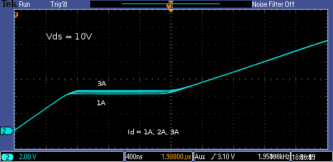
The effect is quite subtle, but It lifts the plateau a small amount as the current increases.
Now, here's what happens if I keep the current at 1A and change Vds.

I was pleased with all those. Sometimes experimenting doesn't go very well, but this time it worked quite nicely.
Although I'm mostly just replicating what's on the datasheet, it has given me a better appreciation of how the Vgs versus total gate charge curve changes with drain voltage and drain current. Sometimes datasheets just show a curve taken with a single value for each which hides from you the effect of changing either if you're not too familiar with how the devices work.
If you found this interesting and would like to see more blogs I've written, a list can be found here: jc2048 Blog Index
Top Comments
-

dougw
-
Cancel
-
Vote Up
+2
Vote Down
-
-
Sign in to reply
-
More
-
Cancel
Comment-

dougw
-
Cancel
-
Vote Up
+2
Vote Down
-
-
Sign in to reply
-
More
-
Cancel
Children