


When we are taught about op amps, the usual starting point is a perfect op amp. That amplifier has infinite gain, infinite input resistance on the two inputs, zero output resistance, and so forth. That's done so that the focus can be on understanding the basic operation and how the feedback operates with the various common circuit configurations, without all the messy real- world details that apply to an actual physical circuit. Although real op amps can be very, very good (exceptionally so compared to what most of us would end up with if we tried to design one with discrete parts), inevitably they fall short of perfection, so we need to understand those imperfections and how much real effect they have in order to design with them.
One such imperfection is input offset voltage. An ideal op amp would have zero offset voltage. That is, the difference in voltage between the two inputs would be zero to get zero at the output. In practice the manufacturer can't achieve that. That might be because of small differences between the characteristics of the input transistors, or it might be because the internal circuit isn't perfectly balanced leading to a slight offset by design. The net result of that offset, from our point of view as designers is that it's as though the perfect op amp has a small voltage generator in series with one input. That then upsets the operation of our circuits a little bit. For precision work, we may want to pay more for a precision op amp that has much tighter specs for input offset voltage.
So how to look at it and measure it? This was going to be easy, I thought. Dredged up from the rank depths of my memory was a circuit that would show me not only the input voltage offset but also the open-loop gain and how close to the rails the outputs could get. I don't know where I might have seen it and can't find it now. It might have been a book, an application note, or maybe even online. Or maybe I imagined it.
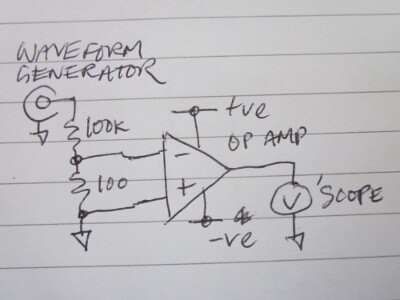
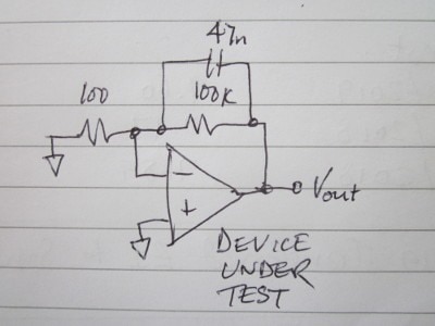
The circuit was something like this
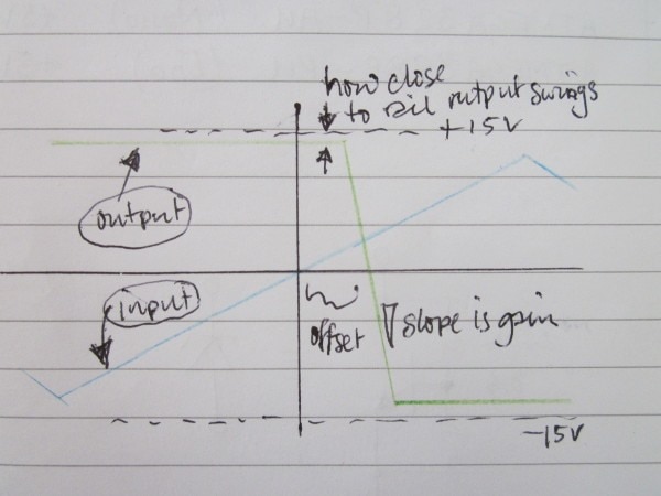
and the result would be along these lines:
The input is a triangle wave and is simply attenuated by a factor of approximately 1000 by the resistors, giving better control of the mV-level signal at the input.
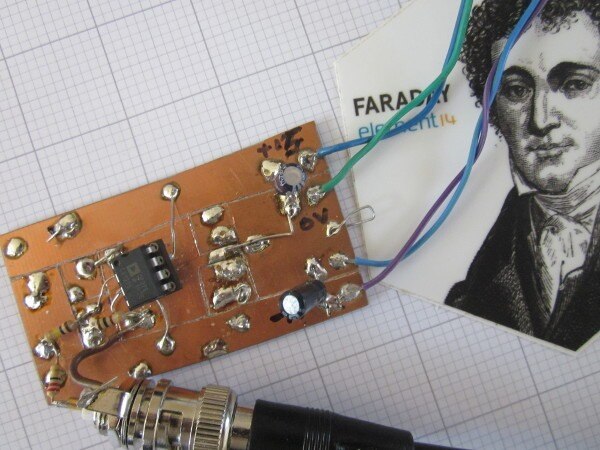
I should have thought a bit harder about what the result might be but, in a fit of enthusiasm, I quickly repurposed one of my old test pcbs
and tried it on some of the odd selection of op amps I've accumulated over the last couple of years.
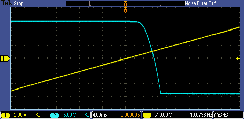
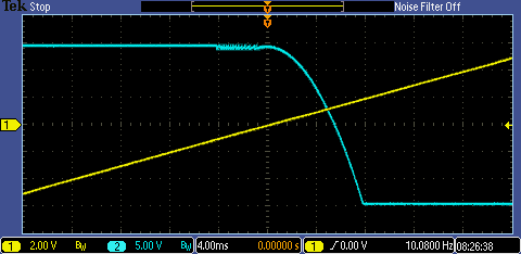
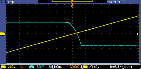
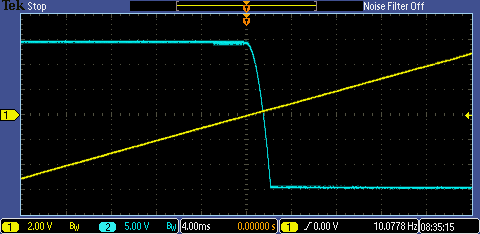
Here are the results
TL081
OP177
ICL7611 [powered from +8v, -8V rails]
OP27
They look plausible but there's a snag. I can't show you because I didn't save a trace of it, but the output always lagged the input zero-crossing point, irrespective of whether the input was on the ramp up or the ramp down. If it represented the offset, it would have lead one way and lagged the other. So what am I looking at? A further clue is the rounded corner where the output starts to move. I'm looking at how the op amp output behaves when it comes out of limiting at the rail, and it doesn't hurry, does it? The plots do show me how close the outputs can get to the rail, so it wasn't a total fail as an experiment. The results are fine for showing how the parts behave as comparators [not too good, if you like fast and snappy], but the offset is quite overshadowed by the slow recovery.
At that point I decided to change course and rewired the board like this
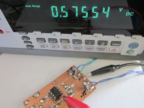
Now the op amp is simply amplifying the offset voltage and I can read it on a bench meter. Here are the results for the same four op amps
TL081 FET-input bipolar. Typ: 3mV Max: 15mV Reads: 576uV
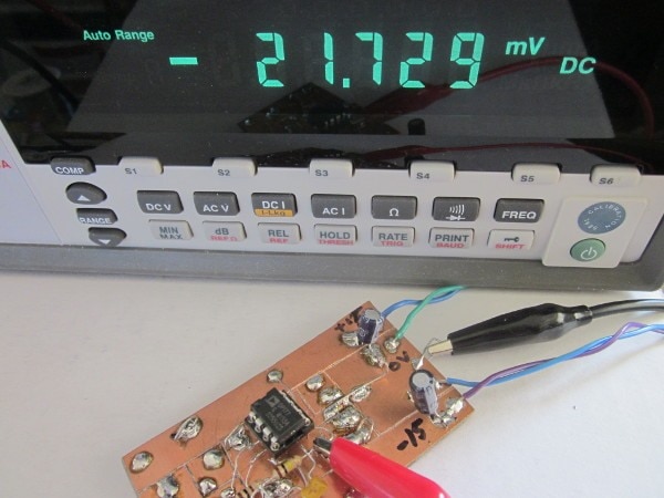
OP177 Precision bipolar. Typ: 20uV Max:60uV Reads 22uV
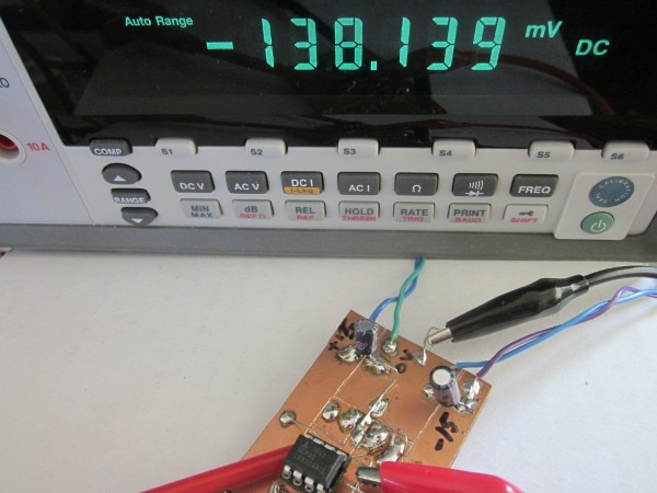
ICL7611 CMOS Typ: Not Given Max: 15mV Reads: 138uV (Iq was set to 1mA)
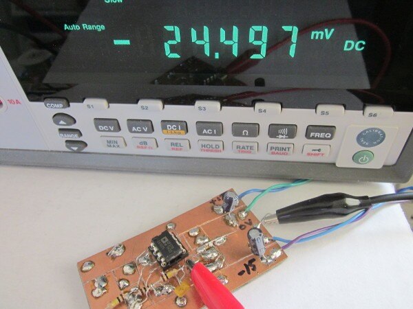
OP27 Precision bipolar. Typ: 30uV Max: 100uV Reads: 25uV
The reading on the meter is 1000 times the offset.
(More or less: strictly the gain is 1001, the resistors are only 5%, and there must be a small contribution to drive the output to the measured voltage, though it won't be very much. So all in all a little approximate, but good enough for a quick blog.)
The precision parts [OP27 and OP177] lived up to their billing, being close to their typical figures. The FET-input TL081 was worst, but well within spec and better than might have been expected [it has offset pins, so could be trimmed closer, though, with a lot of the applications it gets used for, it wouldn't be an issue anyway]. The CMOS part was a lot better than the datasheet allows for - so it looks like I got lucky with that one too.
What would be interesting would be to look at the spread on a group of similar parts, but unfortunately I don't have a lot of op amps so that will have to wait for another day.
If you found this interesting and would like to see more blogs I've written, a list can be found here: |
References
[1] User's Guide to Applying and Measuring Operational Amplifier Specifications
Ray Stata, Analog Devices Application Note AN-356
Note that that derives from something published in1967, so the methods that manufacturers use now may be much more spohisticated.
Top Comments