Following on from earlier discussions I thought I'd take a look at how easy (or not) it is to use a big MOSFET in a simple set up to switch a 5A load to test power supply transient response:
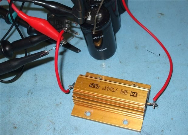
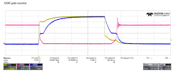
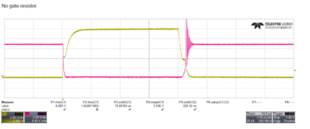
I used an STW60N10 MOSFET, a 3.3R load resistor, 4 x 4700 uF 100V caps in parallel. The MOSFET is driven from Rigol 1030Z signal generator set to make 20uS pulse at 100Hz rate. I tried it with and without a 100R resistor in the gate.
The power supply was 16.5V via a100R resistor driving the capacitor bank.
Here's a picture:
And these are the results:
Red trace is MOSFET drain voltage, Yellow trace is Sig gen output, Blue trace is MOSFET gate.
It's fairly horrible - the stray inductance in the load makes it ring when the MOSFET switches off and it turns out to be quite tricky to control this (using only passives and a sig gen for the drive pulses.)
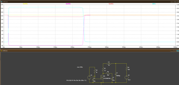
Time for an LTSPice model:
The magenta trace is the MOSFET drain voltage, the blue the current though R1 and the red is the voltage on C1 (which dips due to C1 series resistance)
R3 and C3 slow down the drive to the MOSFET, R4 and C2 'snub' the high frequency ringing when the load inductance is small.
L1 is the load inductance - this ciruit isn't too bad for values up to about 20uH.
If you are interested then run the model in LT SPice - it's free and try some tuning of your own - no prizes 
MK


-

D_Hersey
-
Cancel
-
Vote Up
0
Vote Down
-
-
Sign in to reply
-
More
-
Cancel
Comment-

D_Hersey
-
Cancel
-
Vote Up
0
Vote Down
-
-
Sign in to reply
-
More
-
Cancel
Children