


A simple low signal / audio "soft" switch with a p-channel JFET. It's very easy to make, with common components. Low power.
The circuit is published on neatcircuits.com |

I've ordered a set of transistors to play with. One of them is a ON Semiconductor (Fairchild) J176.
This is a small signal P-channel JFET, designed for analog switching.
Let's first look at the circuit in the DC domain, with the switch open.
Both drain and source are kept to ground by the 330K resistorsat input and output.
The gate is pulled to the supply voltage (5 - 15 V). The transistor is open (very high resistance).
When the switch is closed, the gate is 1 diode drop above ground and above drain and source.
The transistor is closing and input signal can flow to the output.
Typically, you'd use an open collector type digital output instead of a mechanical switch.
Attention: The circuit is a bit rough here, because the full charge of the 1 µF capacitor (used to silence the switch) is dumped through diode and switch circuit.
In the AC domain, let's check what's possible:
We can derive the amplitude of the signal that can be switched from the datasheet - a subject for a follow up post.
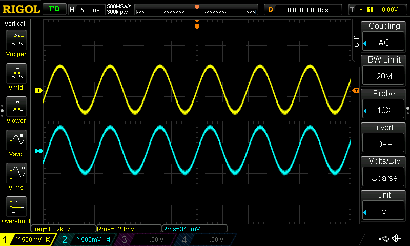
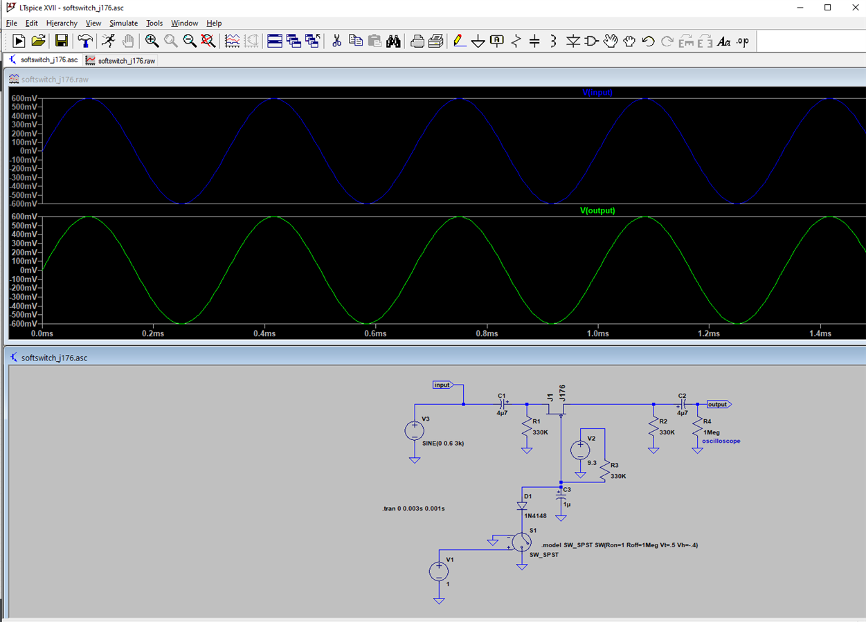
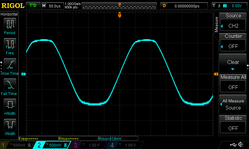
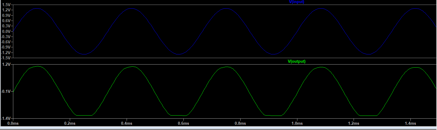
In this post, let's compare what I see on an oscilloscope with the switch closed (yellow is input, blue is output) with a simulation in LTspice (blue is input, green is output):
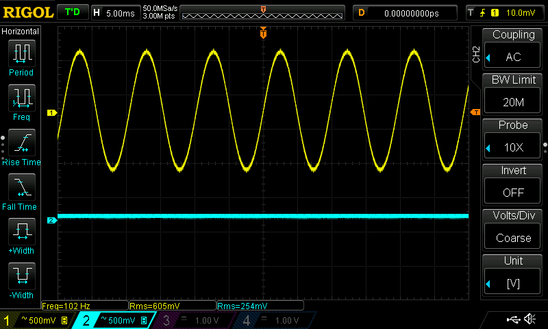
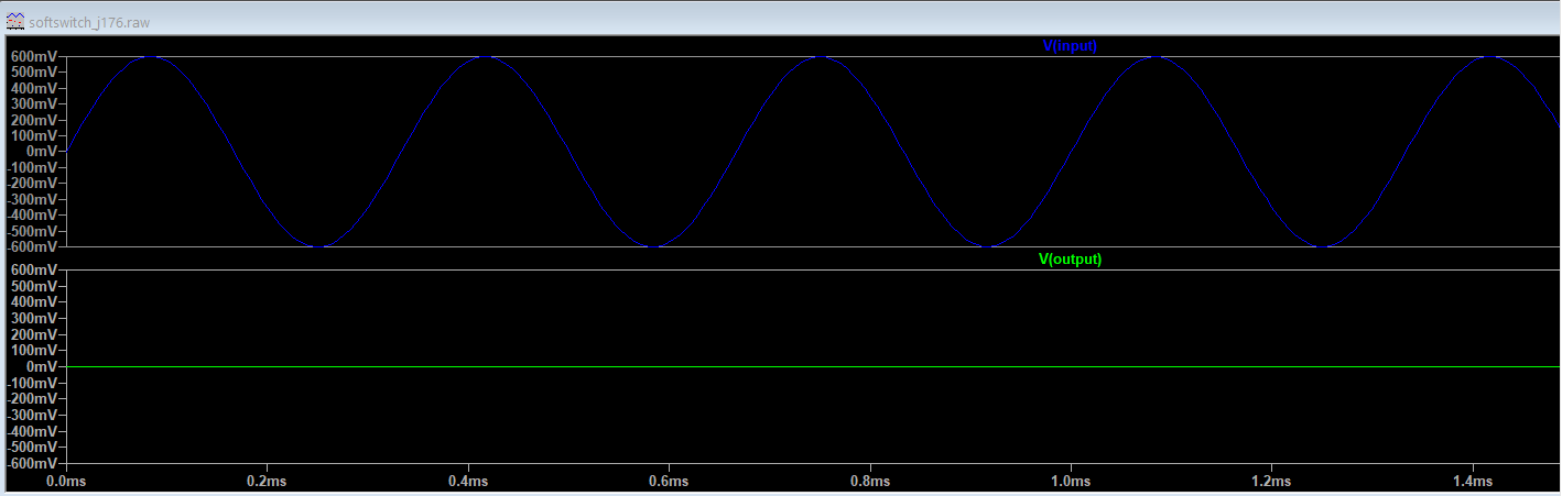
.... and with the switch open:
This switch operates in the linear region of the FET.
That's a small part of the operational region where the relationship between VDS and IDS acts like a voltage controlled resistor.
We're using that region in its two extremes: maximum resistance and minimum resistance.
Preview for the next post: limits of the input signal amplitude. This is what the system looks like with an input amplitude of 1.2 V:
The LTspice project is attached.
| Related blog |
|---|
| Simple analog JFET switch - part 1: schema, simulate and test |
| Simple analog JFET switch - part 2: linear range and limitations |
Top Comments