element14 Community
element14 Community
    Register Log In
  • Site
  • Search
  • Log In Register
  • About Us
  • Community Hub
    Community Hub
    • What's New on element14
    • Feedback and Support
    • Benefits of Membership
    • Personal Blogs
    • Members Area
    • Achievement Levels
  • Learn
    Learn
    • Ask an Expert
    • eBooks
    • element14 presents
    • Learning Center
    • Tech Spotlight
    • STEM Academy
    • Webinars, Training and Events
    • Learning Groups
  • Technologies
    Technologies
    • 3D Printing
    • FPGA
    • Industrial Automation
    • Internet of Things
    • Power & Energy
    • Sensors
    • Technology Groups
  • Challenges & Projects
    Challenges & Projects
    • Design Challenges
    • element14 presents Projects
    • Project14
    • Arduino Projects
    • Raspberry Pi Projects
    • Project Groups
  • Products
    Products
    • Arduino
    • Avnet Boards Community
    • Dev Tools
    • Manufacturers
    • Multicomp Pro
    • Product Groups
    • Raspberry Pi
    • RoadTests & Reviews
  • Store
    Store
    • Visit Your Store
    • Choose another store...
      • Europe
      •  Austria (German)
      •  Belgium (Dutch, French)
      •  Bulgaria (Bulgarian)
      •  Czech Republic (Czech)
      •  Denmark (Danish)
      •  Estonia (Estonian)
      •  Finland (Finnish)
      •  France (French)
      •  Germany (German)
      •  Hungary (Hungarian)
      •  Ireland
      •  Israel
      •  Italy (Italian)
      •  Latvia (Latvian)
      •  
      •  Lithuania (Lithuanian)
      •  Netherlands (Dutch)
      •  Norway (Norwegian)
      •  Poland (Polish)
      •  Portugal (Portuguese)
      •  Romania (Romanian)
      •  Russia (Russian)
      •  Slovakia (Slovak)
      •  Slovenia (Slovenian)
      •  Spain (Spanish)
      •  Sweden (Swedish)
      •  Switzerland(German, French)
      •  Turkey (Turkish)
      •  United Kingdom
      • Asia Pacific
      •  Australia
      •  China
      •  Hong Kong
      •  India
      •  Korea (Korean)
      •  Malaysia
      •  New Zealand
      •  Philippines
      •  Singapore
      •  Taiwan
      •  Thailand (Thai)
      • Americas
      •  Brazil (Portuguese)
      •  Canada
      •  Mexico (Spanish)
      •  United States
      Can't find the country/region you're looking for? Visit our export site or find a local distributor.
  • Translate
  • Profile
  • Settings
Engineering Life
  • Community Hub
  • More
Engineering Life
Forum Dimmer repair
  • Blog
  • Forum
  • Documents
  • Polls
  • Files
  • Members
  • Mentions
  • Sub-Groups
  • Tags
  • More
  • Cancel
  • New
Join Engineering Life to participate - click to join for free!
Actions
  • Share
  • More
  • Cancel
Forum Thread Details
  • Replies 77 replies
  • Subscribers 40 subscribers
  • Views 10841 views
  • Users 0 members are here
Related

Dimmer repair

wal_e
wal_e over 4 years ago

Hello everyone,

First of all I would like to apologize, I might certainly be in the wrong section, but I have been sent here by the Farnell technical assistance and to be honnest this place is a real maze for me image

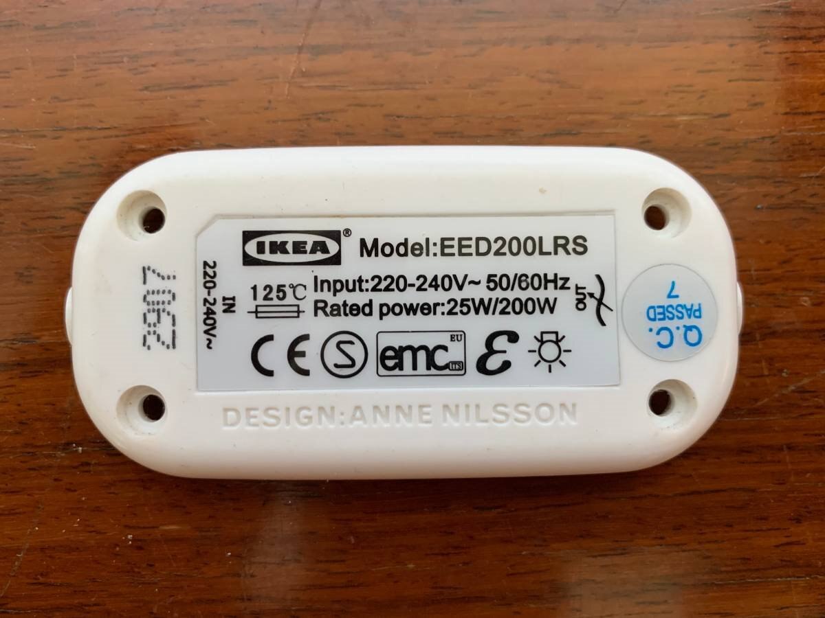
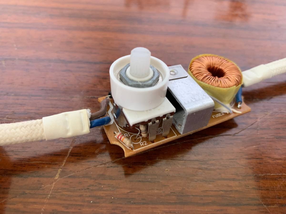
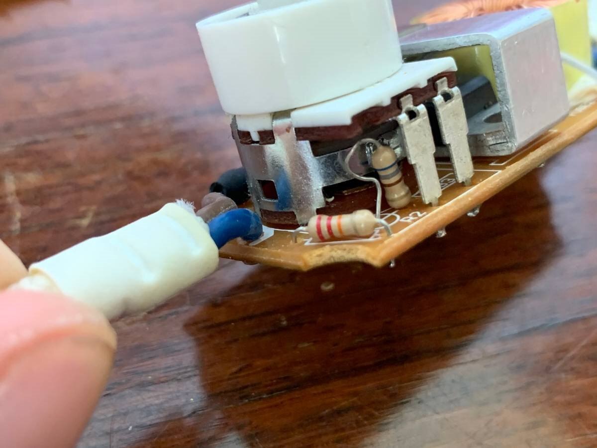
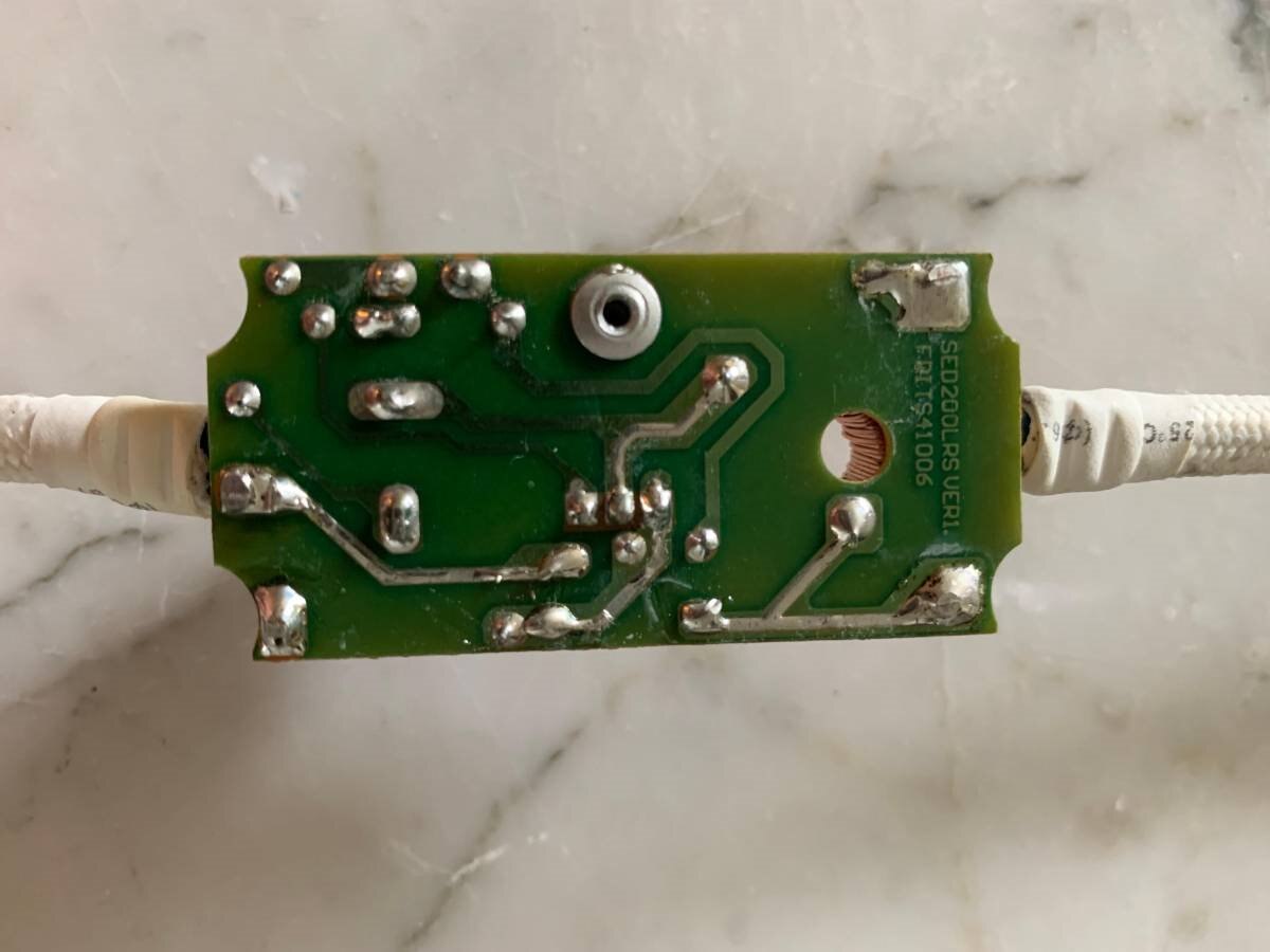
So, I have been trying to fix a dimmer that went working only as a simple switch : OFF to ON max light directly. Following my researches it seems that the origin of my problem is a faulty triac and also - maybe - a capacitor ; I have tested both of the 2 fuses and they are ok.

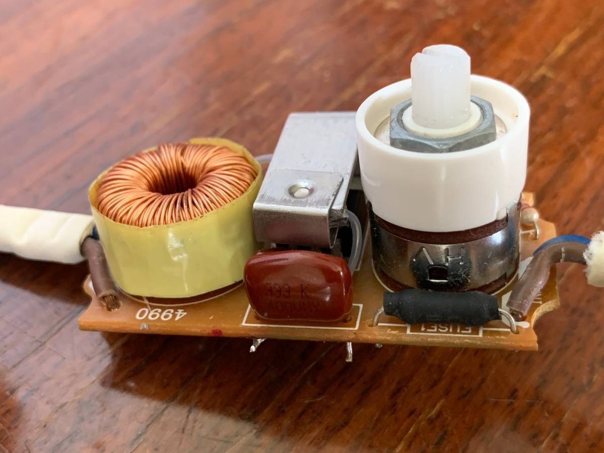
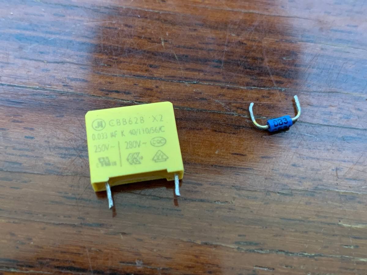
The two original component are labeled:

- BTB04-600A

- CBB62B X2 0.033µF (250-280VAC) dimensions 40/110/56/C

My problem is that I can't find any of the exact two components and I have no idea what I can use to replace them as equivalent.

Any help is really appreciated

Thank you - very much - in advance.


W

  • Sign in to reply
  • Cancel

Top Replies

  • shabaz
    shabaz over 4 years ago +5
    Hi, If rotating the dimmer makes it turn the light on and off, then why do you think the triac is faulty? Couldn't it be the rotary potentiometer? (I don't know - I'm speculating). I'm not sure it is good…
  • jw0752
    jw0752 over 4 years ago +4
    Hi Walid, If you only have off and on and when the dimmer is in the on position it is always at full brightness then the most likely problem is the Triac. You can test this with a continuity tester when…
  • wal_e
    wal_e over 4 years ago in reply to shabaz +4
    Hello Shabaz, Thank you for taking the time to answer. I found this diagnostic on the internet, it says that if the dimmer only works from OFF to ON max power it's a triac issue. As you can imagine this…
Parents
  • jw0752
    jw0752 over 4 years ago

    Hi Walid,


    If you only have off and on and when the dimmer is in the on position it is always at full brightness then the most likely problem is the Triac. You can test this with a continuity tester when the dimmer is removed from power by checking the continuity between A1 and A2 terminals. It should be open under normal circumstances. If it is shorted then the triac is bad. The other components are probably OK. The BTB 04-600A is a 4 Amp 600 Volt triac and can be replaced with pretty much any triac that has ratings of more than 4 amps and 600 volts. I have some BTB 06-600 which would be 6 amps and 600 volts. If you are inside the USA I will send one to you. If you are looking at the triac with the pins down and the label facing you the A1 and A2 terminal are the left pin and the center pin. The right pin is the gate and should be attached to a DB3 trigger diode if you have a standard design.


    John

    • Cancel
    • Vote Up +4 Vote Down
    • Sign in to reply
    • Cancel
  • wal_e
    wal_e over 4 years ago in reply to jw0752

    Hi John,

    Thank you for your help I really appreciate your kind answer but I am too far from you that would make this triac very expensive image So, I am experiencing exactly what you described and already replaced the old triac with a new one labeled BTB08-600BW (the only "equivalent" triac I found in the neiborhood) which didn'ty solve the problem. So I just tested both of them and both of their A1 and A2 show no continuity....does that mean they're both open and ok ? When I tested the capacitor I got a 0.0µF instead of 0.033µF...is it possible that my tester is not sensitive enough or is my capacitor is dead ? In that case could he be the origin of the problem ?

    Best regards,


    W

    • Cancel
    • Vote Up +3 Vote Down
    • Sign in to reply
    • Cancel
  • wal_e
    wal_e over 4 years ago in reply to jw0752

    Good question indeed, I am using a regular incandescent bulb.

    • Cancel
    • Vote Up +1 Vote Down
    • Sign in to reply
    • Cancel
  • jw0752
    jw0752 over 4 years ago in reply to wal_e

    Hi Walid,


    In order to do some experimenting I built a dimmer circuit on bread board.


    You don't have permission to edit metadata of this video.
    Edit media
    x
    image
    Upload Preview
    image


    The first thing I learned from doing this is that my explanation of the circuit a few posts ago was at best simplistic and probably incorrect. My Experiments indicate that your Diac is likely OK. The capacitor value is fairly critical. Too much capacitance and the light stays on high. Too little capacitance and the light stays on high. No capacitance and the light stays off. Shorted Diac or one with parallel resistance and the light stays off. No Diac in circuit and the light stays off. I am sorry as this may not simplify or help much. If you have experiments that you would like me to run let me know. I will leave the bread board assembled for a few days.


    John

    • Cancel
    • Vote Up +2 Vote Down
    • Sign in to reply
    • Cancel
  • jw0752
    jw0752 over 4 years ago in reply to wal_e

    Tonight I hooked up the oscilloscope as I wanted to see the change in the signal on the gate of the triac as the potentiometer was turned from a dim setting to a bright one. Channel one (Yellow) shows the source AC voltage and syncs the horizontal trace. Channel two (blue) is the gate of the triac and the trace on the Hantek Scope is across the bulb. Note the RMS voltage as we go from very dim to full brightness.


    imageimage


    Dim Setting


    imageimage


    Bright Setting


    Note of Caution. Taking readings of AC line voltage can be dangerous. I used an isolated bench AC source for this experiment and a portable secondary scope so than I would not have an Earth or Common ground conflict.


    John

    • Cancel
    • Vote Up +3 Vote Down
    • Sign in to reply
    • Cancel
  • wal_e
    wal_e over 4 years ago in reply to jw0752

    Hi John,

    I am really glad to see that here are persons like you whom put all that effort to help others. So, I changed the Diac and nothing changed still from Off to On full brightness. This, with your last message about the importance of capacitance lead me to think that, in fine, it's the capacitor that's dead or faulty and unfortunatly I couldn't find the exact same one to replace it. I took some photos of the controller and the DMM I borrowed from a friend so if you have any suggestions or ideas please let me know, I would be happy to explore further more.

    Best regards,


    Walid

    image

    image

    image

    image

    image

    image

    image

    • Cancel
    • Vote Up +1 Vote Down
    • Sign in to reply
    • Cancel
  • Jan Cumps
    Jan Cumps over 4 years ago in reply to wal_e

    If you put the DMM in the 200 nF range,it should give a good measurement of that cacitor. : The value 33 - or something within 10% of that.

    You need to fit the capacitor legs into the 2 slots with capacitor symbol.

    Discharge the capacitor first.


    It's indeed a good DMM.

    • Cancel
    • Vote Up +1 Vote Down
    • Sign in to reply
    • Cancel
  • wal_e
    wal_e over 4 years ago in reply to Jan Cumps

    Hi Jan,

    I tested both: brown one on the PCB and the yellow - original one, they both read 00.0 µF :/ I am even starting to doubt the DMM....

    • Cancel
    • Vote Up +1 Vote Down
    • Sign in to reply
    • Cancel
  • wal_e
    wal_e over 4 years ago in reply to wal_e

    I found this page which I think is quite interesting and clear :

    https://www.astuces-pratiques.fr/electronique/variateur-a-triac-fonctionnement-et-schema

    • Cancel
    • Vote Up 0 Vote Down
    • Sign in to reply
    • Cancel
  • Jan Cumps
    Jan Cumps over 4 years ago in reply to wal_e

    image

    Is this how you measured them? If yes, I think they are defect.

    • Cancel
    • Vote Up 0 Vote Down
    • Sign in to reply
    • Cancel
  • colporteur
    colporteur over 4 years ago in reply to jw0752

    Good call on your note of caution JW. Nastie sparks can happen when you fail to recognize the isolation.

    • Cancel
    • Vote Up 0 Vote Down
    • Sign in to reply
    • Cancel
  • jw0752
    jw0752 over 4 years ago in reply to wal_e

    I would like to know if the lamp lights with the DIAC out of the circuit.


    John

    • Cancel
    • Vote Up 0 Vote Down
    • Sign in to reply
    • Cancel
Reply
  • jw0752
    jw0752 over 4 years ago in reply to wal_e

    I would like to know if the lamp lights with the DIAC out of the circuit.


    John

    • Cancel
    • Vote Up 0 Vote Down
    • Sign in to reply
    • Cancel
Children
  • wal_e
    wal_e over 4 years ago in reply to jw0752

    No John, the light stays off whithout the DIAC...

    • Cancel
    • Vote Up 0 Vote Down
    • Sign in to reply
    • Cancel
  • jw0752
    jw0752 over 4 years ago in reply to wal_e

    Thanks for running the experiment which confirms that the Triac is OK and that the Diac is also OK.  Verify that the resistors have the proper values and then the only thing left is the capacitor.


    John

    • Cancel
    • Vote Up 0 Vote Down
    • Sign in to reply
    • Cancel
  • wal_e
    wal_e over 4 years ago in reply to jw0752

    So here are the mesured values:

    C1 (yellow original one) labeled 0.033 µF reads 3.1 when DMM on 200 nF

    C2 (small capacitor behind the big one) labeled 683K reads 70.1 when DMM on 200 nF


    R1 (red, red, orange, silver or grey) supposed to be 22 Kohm reads 0.02 when DMM on 2 Mohm

    R2 (blue, grey, brown, gold) supposed to be 0.68 Kohm reads 0.665 when DMM on 2 Kohm

    • Cancel
    • Vote Up 0 Vote Down
    • Sign in to reply
    • Cancel
  • Jan Cumps
    Jan Cumps over 4 years ago in reply to wal_e

    C1 is not OK

    C2, R1 and R2 measurements are OK

    • Cancel
    • Vote Up 0 Vote Down
    • Sign in to reply
    • Cancel
  • wal_e
    wal_e over 4 years ago in reply to Jan Cumps

    Thank you for the feedback Jan, problem is from what I understood C2, R1 and R2 are part of the main syteme that works to dim the light...C1 and the coil are here to reduce the amount of parasites emitted by the Triac and thus are "optional"....still the system doesn't work...

    • Cancel
    • Vote Up 0 Vote Down
    • Sign in to reply
    • Cancel
  • jw0752
    jw0752 over 4 years ago in reply to wal_e

    What is minimum and maximum resistance of the control?

    • Cancel
    • Vote Up 0 Vote Down
    • Sign in to reply
    • Cancel
  • wal_e
    wal_e over 4 years ago in reply to jw0752

    Can you please be more specific ?

    • Cancel
    • Vote Up 0 Vote Down
    • Sign in to reply
    • Cancel
  • jw0752
    jw0752 over 4 years ago in reply to wal_e

    The knob that you turn to select dim or bright is a variable resistor. It has two terminals that attach at the edge of the board.  When it is at dim I would expect a reading of several hundred K Ohms . When it is at the bright position I would expect a low Ohm reading.

    John

    • Cancel
    • Vote Up 0 Vote Down
    • Sign in to reply
    • Cancel
  • wal_e
    wal_e over 4 years ago in reply to jw0752

    That knob is also used to go from OFF to min light, at that point (even when in off position) it reads 14.6 when DMM is in 20 Kohm and when max bright light it reads 1.8 when DMM is in 200 ohm.

    • Cancel
    • Vote Up 0 Vote Down
    • Sign in to reply
    • Cancel
  • jw0752
    jw0752 over 4 years ago in reply to wal_e

    See if you can remove the solder from one leg of the control so that it is separated from the circuit trace. Try the dimmer with power on. The light should stay off. Unplug the unit and check the resistance of the control again with the one leg still detached. When you read the meter watch to see if a "K" is displayed with the number on the display. What are the minimum and maximum position resistances?


    John

    • Cancel
    • Vote Up 0 Vote Down
    • Sign in to reply
    • Cancel
element14 Community

element14 is the first online community specifically for engineers. Connect with your peers and get expert answers to your questions.

  • Members
  • Learn
  • Technologies
  • Challenges & Projects
  • Products
  • Store
  • About Us
  • Feedback & Support
  • FAQs
  • Terms of Use
  • Privacy Policy
  • Legal and Copyright Notices
  • Sitemap
  • Cookies

An Avnet Company © 2025 Premier Farnell Limited. All Rights Reserved.

Premier Farnell Ltd, registered in England and Wales (no 00876412), registered office: Farnell House, Forge Lane, Leeds LS12 2NE.

ICP 备案号 10220084.

Follow element14

  • X
  • Facebook
  • linkedin
  • YouTube