element14 Community
element14 Community
    Register Log In
  • Site
  • Search
  • Log In Register
  • About Us
  • Community Hub
    Community Hub
    • What's New on element14
    • Feedback and Support
    • Benefits of Membership
    • Personal Blogs
    • Members Area
    • Achievement Levels
  • Learn
    Learn
    • Ask an Expert
    • eBooks
    • element14 presents
    • Learning Center
    • Tech Spotlight
    • STEM Academy
    • Webinars, Training and Events
    • Learning Groups
  • Technologies
    Technologies
    • 3D Printing
    • FPGA
    • Industrial Automation
    • Internet of Things
    • Power & Energy
    • Sensors
    • Technology Groups
  • Challenges & Projects
    Challenges & Projects
    • Design Challenges
    • element14 presents Projects
    • Project14
    • Arduino Projects
    • Raspberry Pi Projects
    • Project Groups
  • Products
    Products
    • Arduino
    • Avnet Boards Community
    • Dev Tools
    • Manufacturers
    • Multicomp Pro
    • Product Groups
    • Raspberry Pi
    • RoadTests & Reviews
  • Store
    Store
    • Visit Your Store
    • Choose another store...
      • Europe
      •  Austria (German)
      •  Belgium (Dutch, French)
      •  Bulgaria (Bulgarian)
      •  Czech Republic (Czech)
      •  Denmark (Danish)
      •  Estonia (Estonian)
      •  Finland (Finnish)
      •  France (French)
      •  Germany (German)
      •  Hungary (Hungarian)
      •  Ireland
      •  Israel
      •  Italy (Italian)
      •  Latvia (Latvian)
      •  
      •  Lithuania (Lithuanian)
      •  Netherlands (Dutch)
      •  Norway (Norwegian)
      •  Poland (Polish)
      •  Portugal (Portuguese)
      •  Romania (Romanian)
      •  Russia (Russian)
      •  Slovakia (Slovak)
      •  Slovenia (Slovenian)
      •  Spain (Spanish)
      •  Sweden (Swedish)
      •  Switzerland(German, French)
      •  Turkey (Turkish)
      •  United Kingdom
      • Asia Pacific
      •  Australia
      •  China
      •  Hong Kong
      •  India
      •  Korea (Korean)
      •  Malaysia
      •  New Zealand
      •  Philippines
      •  Singapore
      •  Taiwan
      •  Thailand (Thai)
      • Americas
      •  Brazil (Portuguese)
      •  Canada
      •  Mexico (Spanish)
      •  United States
      Can't find the country/region you're looking for? Visit our export site or find a local distributor.
  • Translate
  • Profile
  • Settings
Community Hub
Community Hub
Member's Forum Breadboarding a must
  • Blog
  • Forum
  • Documents
  • Quiz
  • Events
  • Leaderboard
  • Polls
  • Files
  • Members
  • Mentions
  • Sub-Groups
  • Tags
  • More
  • Cancel
  • New
Join Community Hub to participate - click to join for free!
Actions
  • Share
  • More
  • Cancel
Forum Thread Details
  • Replies 17 replies
  • Subscribers 532 subscribers
  • Views 2467 views
  • Users 0 members are here
Related

Breadboarding a must

Andrew J
Andrew J over 5 years ago

Really, you gotta breadboard, right?


image

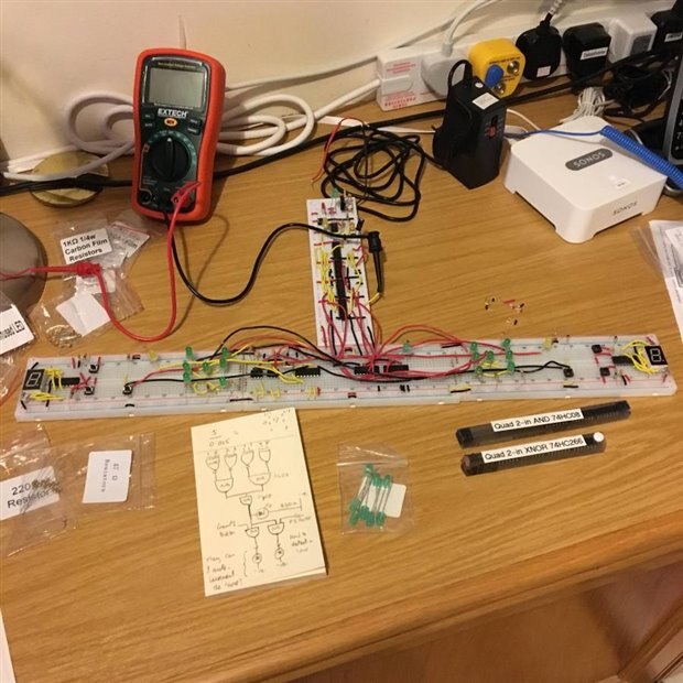
This is a logic-driven game of snap, but with dice rather than cards.  It uses a XNOR!  If I remember correctly, that sketch on the post-it was for detecting and determining a match on the two LED die, turning on a player's led if they pressed the button correctly before the other player (and not if they didn't.)  I'd post a circuit diagram but about 1/4 of this is Charles Platt's work not mine so I don't feel it would be right.  I just came across the photo today and thought it was quite impressive - I keep thinking of going back to it and actually building it up and encasing.  It actually drove one of my very first questions on Element14 - I'd used an open-drain XNOR and didn't understand why it wasn't working.

  • Sign in to reply
  • Cancel

Top Replies

  • michaelkellett
    michaelkellett over 5 years ago in reply to cstanton +8
    And before anyone asks - that jar has 4 months to go before EOL ! @ Christopher, not electrically conductive as we know it ! MK
  • kmikemoo
    kmikemoo over 5 years ago +7
    Andrew J Awesome layout. Honestly... I wish I put my projects to breadboard move often than I do. If I think the circuit is "simple", I go straight to protoboard - and often regret the layout. NOTHING…
  • cstanton
    cstanton over 5 years ago in reply to Andrew J +7
    I hear marmite is electrically conductive.
  • michaelkellett
    michaelkellett over 5 years ago

    I've never been a bread-boarder - don't even own one !


    In the past I've done a fair bit with Veroboard (strip-board if you prefer) and I still use that occasionally.


    Normally I do simulation (logic in VHDL which will end up on an FPGA and analogue in LTSpice ) and then straight to pcb.


    Stuff that will work on bread-board will usually simulate nicely. Fancy analogue and switching or high power analogue don't work well on bread-board (and can be tricky in simulation).


    BTW, if you don't like LTSpice then you can now get MicroCap for free - it was a quite well thought of paid for simulator - now it's a free download at http://www.spectrum-soft.com


    This is a typical bread-board unfriendly device - it's a 2ns pulse stretcher with adjustable input threshold - simulates OK and works on a pcb but would not be feasible in other formats.


    None of the chips I want to use come in DIP any more image


    image


    MK

    • Cancel
    • Vote Up +6 Vote Down
    • Sign in to reply
    • Cancel
  • Andrew J
    Andrew J over 5 years ago in reply to michaelkellett

    It does seem that more and more chips are SMD only and the adaptors to use aren’t particularly cheap - I’ve thought it would be useful to cram them into spare PCB space when getting one manufactured.  At the time I created the above, breadboards, hook up wire and DIP chips/TH parts were all I had.  And a 9V/12V wall wart to drive them.


    I downloaded Microcap a week or so ago but haven’t had chance to play with it yet.  I find LTSpice “OK” but the UI leaves a lot to be desired on the mac.  There’s nothing intuitive about it so I’ve found features purely through serendipity than active knowledge.


    Where I am in my knowledge, I think breadboarding is useful for just trying things out, measuring them and playing around.  Even simple things like an RC circuit.

    • Cancel
    • Vote Up +5 Vote Down
    • Sign in to reply
    • Cancel
  • cstanton
    cstanton over 5 years ago in reply to Andrew J

    I hear marmite is electrically conductive.

    • Cancel
    • Vote Up +7 Vote Down
    • Sign in to reply
    • Cancel
  • shabaz
    shabaz over 5 years ago in reply to Andrew J

    Hi Andrew,


    Even using SMD adapter/proto-boards is time-consuming, sometimes it's easier to go from simulating straight to a PCB. But occasionally for single-chip experiments, I'll use a proto-board, I did try to create a general one to save a bit of money, I'm not sure how useful it is to others since it is mostly personal preferences on the design, but I'm happy to put the gerber files somewhere if anyone wants it. The boards need cutting, there's no bite-marks or anything to split them.

    I'm running low on these layouts (ten of these boards lasted a few years), I need to re-order them too. It's not a great board on balance, because some of the layouts were not useful, e.g. the QFN one at the bottom row, is not helpful because there are so many variants of QFN that it's unlikely to be right for any occasion. Also the bottom-right one with USB and DC jack isn't that useful, it's cheaper to buy USB sockets pre-soldered on boards.

    The only ones I've used a lot, are the top left style (repeated on the bottom row too) which is SOIC up to 20 pins, and the one next to it which can handle SSOP, and the middle row (orange arrow) which handles SOT-23, or the larger SMD 3-pin regulators.

    What worked really well was that the layouts have a ground area (green arrow) underneath, so any pin on the IC can be connected to 0V by running uninsulated wire from a hole to the underside and folding it over into the ground area (there's no solder mask there). Also another thing that worked well was that there are long stretches on each pin with no solder mask (red arrow) where 0603 parts can be soldered across pins for instance.

    The top-right layout was intended for interfacing flat flex, I've used that layout rarely since for circuits with flat flex it is likely I may have a PCB anyway.

    image

    Here's an example of the top-left board with a SOIC-8 chip, you can see the straddled components etc. For series components, I'll cut the trace with a scalpel The centre is ground, connected to the underside. Wires held in place with araldite : )

    image

    An example, showing the SOT-23 and DC jack boards:

    image

    Underside of a few random boards, you can see how bare wires were run into the centre ground:

    image

    It's all a bit crude : ) A sheet of copper-clad can be handy too, as a base and ground plane.

    • Cancel
    • Vote Up +7 Vote Down
    • Sign in to reply
    • Cancel
  • michaelkellett
    michaelkellett over 5 years ago in reply to cstanton

    image


    image


    And before anyone asks - that jar has 4 months to go before EOL !


    @ Christopher, not electrically conductive as we know it !


    MK

    • Cancel
    • Vote Up +8 Vote Down
    • Sign in to reply
    • Cancel
  • Andrew J
    Andrew J over 5 years ago in reply to shabaz

    There's some good ideas in there though, even if you don't use them so much - making multisize ones rather than footprint specific for example.  You've not had any issues with shorting the top and bottom layers when cutting them I guess otherwise you would have mentioned it.  I have gone straight from design/simulation to PCB but I've paid the price on a couple of occasions - it can turn out expensive, e.g. getting 4 layer PCBs fast delivered only to find the inductor footprint was completely wrong.  That was £60 or so I won't be seeing again!! 

    • Cancel
    • Vote Up +5 Vote Down
    • Sign in to reply
    • Cancel
  • mudz
    mudz over 4 years ago

    Me and breadboard are enemies of some kind , seriously. I hate working on breadboards I don't know why but many times it has failed me for reasons -  interconnection burns due to little large flow of current or loose connection joints or breadboard manufacturing defect(happened to me twice) :/ . . My trust on breadboards is long gone.
    Actually, since the beginning I've used pcb and soldering iron for the purpose. So, I'm in a habit of drawing circuit on paper, reconfirm it & draw components layout in my mind usually three to four times before soldering components directly on pcb. Well it worked well for me till now.  image

    Well good work with your breadboard wiring. image

    • Cancel
    • Vote Up +1 Vote Down
    • Sign in to reply
    • Cancel
<
element14 Community

element14 is the first online community specifically for engineers. Connect with your peers and get expert answers to your questions.

  • Members
  • Learn
  • Technologies
  • Challenges & Projects
  • Products
  • Store
  • About Us
  • Feedback & Support
  • FAQs
  • Terms of Use
  • Privacy Policy
  • Legal and Copyright Notices
  • Sitemap
  • Cookies

An Avnet Company © 2025 Premier Farnell Limited. All Rights Reserved.

Premier Farnell Ltd, registered in England and Wales (no 00876412), registered office: Farnell House, Forge Lane, Leeds LS12 2NE.

ICP 备案号 10220084.

Follow element14

  • X
  • Facebook
  • linkedin
  • YouTube