element14 Community
element14 Community
    Register Log In
  • Site
  • Search
  • Log In Register
  • Community Hub
    Community Hub
    • What's New on element14
    • Feedback and Support
    • Benefits of Membership
    • Personal Blogs
    • Members Area
    • Achievement Levels
  • Learn
    Learn
    • Ask an Expert
    • eBooks
    • element14 presents
    • Learning Center
    • Tech Spotlight
    • STEM Academy
    • Webinars, Training and Events
    • Learning Groups
  • Technologies
    Technologies
    • 3D Printing
    • FPGA
    • Industrial Automation
    • Internet of Things
    • Power & Energy
    • Sensors
    • Technology Groups
  • Challenges & Projects
    Challenges & Projects
    • Design Challenges
    • element14 presents Projects
    • Project14
    • Arduino Projects
    • Raspberry Pi Projects
    • Project Groups
  • Products
    Products
    • Arduino
    • Avnet Boards Community
    • Dev Tools
    • Manufacturers
    • Multicomp Pro
    • Product Groups
    • Raspberry Pi
    • RoadTests & Reviews
  • Store
    Store
    • Visit Your Store
    • Choose another store...
      • Europe
      •  Austria (German)
      •  Belgium (Dutch, French)
      •  Bulgaria (Bulgarian)
      •  Czech Republic (Czech)
      •  Denmark (Danish)
      •  Estonia (Estonian)
      •  Finland (Finnish)
      •  France (French)
      •  Germany (German)
      •  Hungary (Hungarian)
      •  Ireland
      •  Israel
      •  Italy (Italian)
      •  Latvia (Latvian)
      •  
      •  Lithuania (Lithuanian)
      •  Netherlands (Dutch)
      •  Norway (Norwegian)
      •  Poland (Polish)
      •  Portugal (Portuguese)
      •  Romania (Romanian)
      •  Russia (Russian)
      •  Slovakia (Slovak)
      •  Slovenia (Slovenian)
      •  Spain (Spanish)
      •  Sweden (Swedish)
      •  Switzerland(German, French)
      •  Turkey (Turkish)
      •  United Kingdom
      • Asia Pacific
      •  Australia
      •  China
      •  Hong Kong
      •  India
      •  Korea (Korean)
      •  Malaysia
      •  New Zealand
      •  Philippines
      •  Singapore
      •  Taiwan
      •  Thailand (Thai)
      • Americas
      •  Brazil (Portuguese)
      •  Canada
      •  Mexico (Spanish)
      •  United States
      Can't find the country/region you're looking for? Visit our export site or find a local distributor.
  • Translate
  • Profile
  • Settings
Community Hub
Community Hub
Member's Forum Diagnosis: GameBoy Advance SP - No Audio
  • Blog
  • Forum
  • Documents
  • Quiz
  • Events
  • Leaderboard
  • Polls
  • Files
  • Members
  • Mentions
  • Sub-Groups
  • Tags
  • More
  • Cancel
  • New
Join Community Hub to participate - click to join for free!
Actions
  • Share
  • More
  • Cancel
Forum Thread Details
  • Replies 9 replies
  • Subscribers 509 subscribers
  • Views 464 views
  • Users 0 members are here
  • audio
  • gameboy advance sp
  • gameboy
  • advance sp
Related

Diagnosis: GameBoy Advance SP - No Audio

cstanton
cstanton over 5 years ago

imageimage


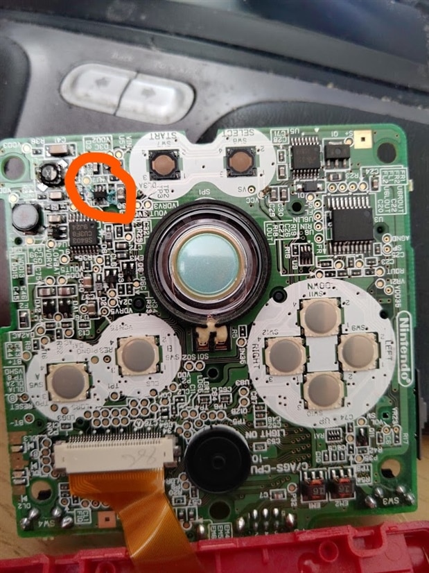
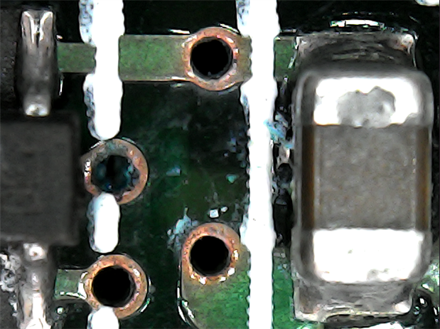
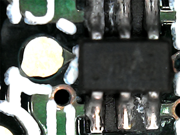
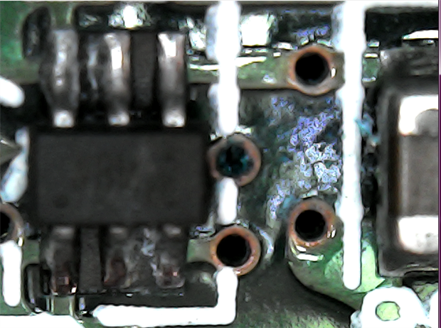
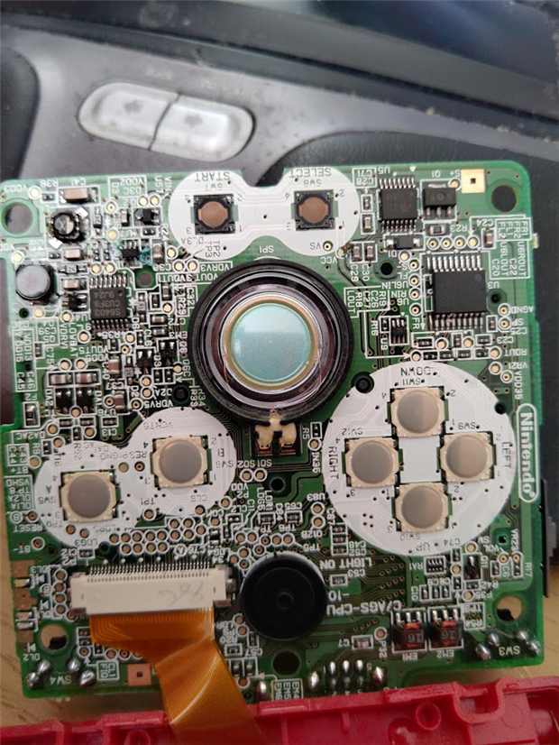
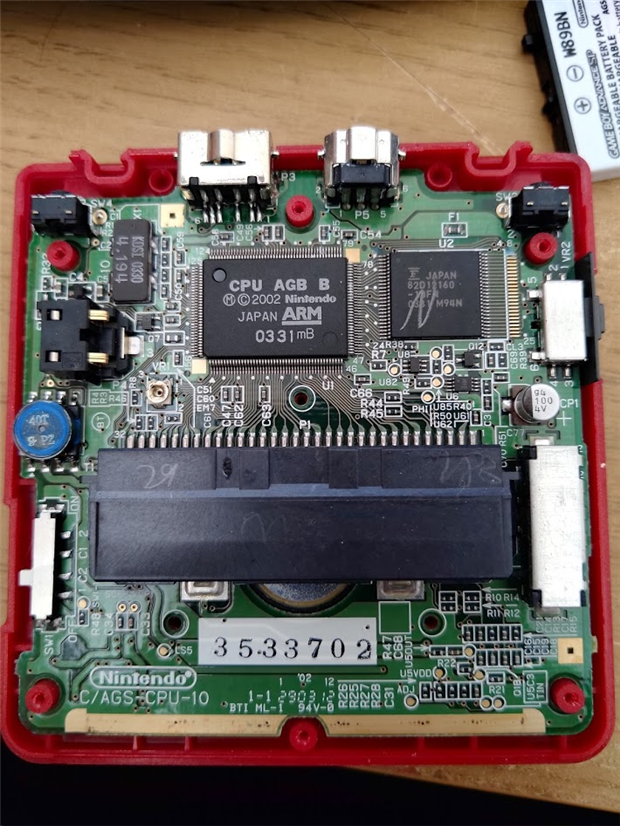
The GameBoy Advance SP works, however there's no audio from the speaker, the SP was different from the Advance in that there's no 3.5mm headphone jack either so I can't easily compare/check it.


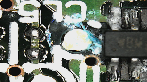
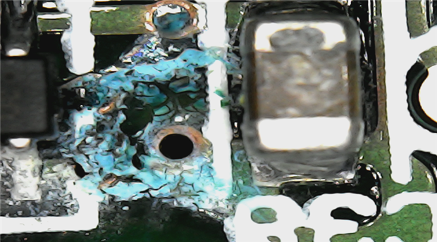
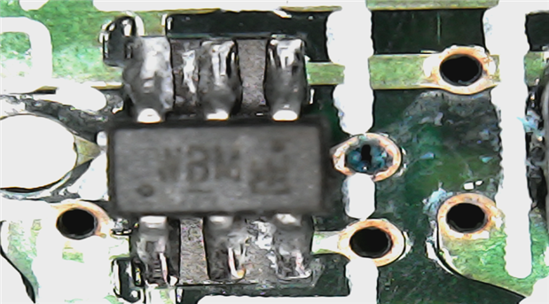
What're the steps I can take to start diagnosing this and where the problem is? I'm not familiar with using an oscilloscope if necessary, though I have a bitscope one I could try to work out how to use. I'm not seeing any physical problems.

  • Sign in to reply
  • Cancel

Top Replies

  • msebok
    msebok over 5 years ago +3
    Whats going on here? looks odd..
  • cstanton
    cstanton over 5 years ago in reply to msebok +2
  • shabaz
    shabaz over 5 years ago +1
    Hi Christopher, The speaker can be checked with a multimeter set to ohms, just to confirm it is ok (should be 100 ohm or lower resistance across the terminals of it) and just confirm it's still soldered…
  • shabaz
    shabaz over 5 years ago

    Hi Christopher,


    The speaker can be checked with a multimeter set to ohms, just to confirm it is ok (should be 100 ohm or lower resistance across the terminals of it) and just confirm it's still soldered or pressed fine onto the board (using the multimeter set to ohms and check the connections on the track if possible, or visually inspect that the speaker is still making good contact with the board).

    Is there a volume control/slider/switch or anything? If so, those can sometimes fail. There a post here which talks about four solder connections on switches could be the issue:

    https://gbatemp.net/threads/gba-sp-sound-not-working.468232/


    For a sound issue, a crystal earpiece is really handy, you can move it around various points on the board, with no risk of damaging anything because the earpiece has a very high resistance so it doesn't load the circuit.

    However, you might not need that, if the issue is solved by the other suggestions above. A 'scope can be used for that too but again I don't think it will be necessary initially.

    • Cancel
    • Vote Up +1 Vote Down
    • Sign in to reply
    • Cancel
  • cstanton
    cstanton over 5 years ago in reply to shabaz

    Finally found batteries for my multimeter...


    7.6ohms across the speaker, appears to make good contact with the PCB (it's stuck to the board with weak glue and prongs make contact). No sound still.


    There's a volume slider, it has 6 solder points and those are very secure to the PCB.


    I don't have a crystal earpiece or another way of testing the speaker at the moment.

    • Cancel
    • Vote Up +1 Vote Down
    • Sign in to reply
    • Cancel
  • shabaz
    shabaz over 5 years ago in reply to cstanton

    Oh, hoped it would have been an easy thing with some failed contacts : (

    The analogue channel on the bitscope could be used, by powering up the unit with a game installed and if it is known that sound should be playing for the game.

    The contacts near the volume slider would need to be probed (with the bitscope ground connection connected to the battery negative contact), and the 'scope set to approx. 1 msec/division or thereabouts, and 0.5 or 1 V/div. Also, probing near any small chip or capacitors that may be part of the audio amplifier circuitry, it could be physically between the speaker and the volume control area, just to spot if the audio signal is detected. There appear to be lots of 3-pin SOT-23 sized parts and some capacitors in that area from the photo, so that might be the amplifier. Probing on the capacitors would be worth trying, and if audio does get spotted in that area, then maybe reheating some of the parts there could fix it (in case a solder joint has lifted due to button-presses flexing the board maybe.

    • Cancel
    • Vote Up +1 Vote Down
    • Sign in to reply
    • Cancel
  • msebok
    msebok over 5 years ago

    Whats going on here? looks odd..

    image

    • Cancel
    • Vote Up +3 Vote Down
    • Sign in to reply
    • Cancel
  • msebok
    msebok over 5 years ago

    https://www.youtube.com/watch?v=iG-8Y6XKZzY


    this guy had the same issue.. found that the speaker when pushed against the contacts worked.. around the 6 minute mark

    • Cancel
    • Vote Up +1 Vote Down
    • Sign in to reply
    • Cancel
  • cstanton
    cstanton over 5 years ago in reply to msebok

    I'll have a closer look at that..

    • Cancel
    • Vote Up +1 Vote Down
    • Sign in to reply
    • Cancel
  • cstanton
    cstanton over 5 years ago in reply to msebok

    Unfortunately the speaker is making good contact with the PCB.

    • Cancel
    • Vote Up +1 Vote Down
    • Sign in to reply
    • Cancel
  • cstanton
    cstanton over 5 years ago in reply to msebok

    imageimage

    imageimage

    imageimage

    • Cancel
    • Vote Up +2 Vote Down
    • Sign in to reply
    • Cancel
  • shabaz
    shabaz over 5 years ago in reply to cstanton

    Hi Christopher,


    It looks like U3 (near the directional pad) is the audio chip, but it's custom so no datasheet. However connections near it could be probed to spot the audio signal, but also worth checking supply rails (there may be a separate analogue and digital supply rail), perhaps identifiable by screenprinting on the board of test points or signal names, or if there is a ground plane. In any case, it appears to be the same chip as on the Gameboy Advance (non-SP), so the schematic will likely be very similar. This is the GBA schematic for that area, and the supply rails can be checked plus the audio at LIN, RIN and the SPKOUT pins. There's also pin 12 which is labelled STB with a bar on top, so that could be inverted standby, and would need to be high for the chip to be enabled.

    image


    The part that Matt identified as looking odd could be water damage, and might be power related (supply regulation or switching a power rail on or off) so could well be the cause too. It might need some some examination or solder re-melting there, if any corrosion has damaged a join or track. I couldn't find what part it was, I think it says WBM on the SOT23-6 shaped part U7, but my attempts to google for it found nothing : (

    • Cancel
    • Vote Up 0 Vote Down
    • Sign in to reply
    • Cancel
element14 Community

element14 is the first online community specifically for engineers. Connect with your peers and get expert answers to your questions.

  • Members
  • Learn
  • Technologies
  • Challenges & Projects
  • Products
  • Store
  • About Us
  • Feedback & Support
  • FAQs
  • Terms of Use
  • Privacy Policy
  • Legal and Copyright Notices
  • Sitemap
  • Cookies

An Avnet Company © 2025 Premier Farnell Limited. All Rights Reserved.

Premier Farnell Ltd, registered in England and Wales (no 00876412), registered office: Farnell House, Forge Lane, Leeds LS12 2NE.

ICP 备案号 10220084.

Follow element14

  • X
  • Facebook
  • linkedin
  • YouTube