


It is well known that the worst form of oscillator to use as a theremin VFO is the RC type - The frequency of these oscillators is simply a function of R*C, and as the "antenna" to hand capacitance follows an inverse square law, pitch (from heterodyning the VFO with a fixed reference oscillator) response (linearity) is the worst possible.
LC oscillators without an equalizing inductor have a better response, and this is greatly improved (in most cases) by adding a suitable series inductor with the antenna..
The circuit presented here has only been evaluated (not extensively) in simulation - It has not yet been built. The objective is to improve the "linearity" of a simple RC oscillator used as a theremin VFO.

In the above implementation which uses a TS555CD.TS555CD. as the oscillator, C1 RV1 and R2 form a 'monostable' type circuit which changes the charging and discharging paths for C2 (the antenna capacitance) - The effect of these components is to increase the frequency as the frequency increases - as in, if C2 reduces, the frequency will increase to a greater degree than would have occurred if C1 had not been present.
Waveforms shown below give a better understanding of the operation:
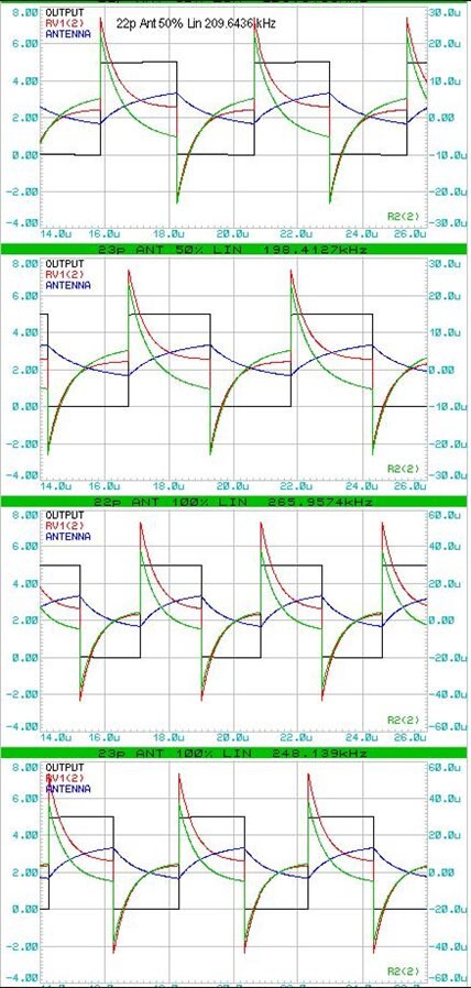
Shown are waveforms for an antenna capacitance of 22pF and 23pF, with linearity control set to 50% and 100%. It should be noted that the Tuning potentiometer (VR) and the linearity potentiometer are highly interactive. For higher VFO frequencies, C1 should be reduced.
 | |
 |


