Theremins + Voltage Control:
Fred Mundell, Fundamental Designs Ltd. 2012 Email fred [at] fundes [dot] co [dot] uk
This article discusses the applications I was working on regarding:
1) Generating, from theremin frequency difference (audio* output), a 1V/Octave control voltage for controlling both internal synthesis circuits and driving external voltage controlled synthesisers and modules, and
2) Converting heterodyning theremins so that they could be controlled by a 1V/Octave control voltage.
At first glance, the above may seem a little pointless – First, (a) CV output is available from several theremins already on the market (including the EW+ and EW-Pro), and (b) why would anyone want to voltage-control a theremin ? I hope to show here that there is good reason for both!
Alas, due to being “interrupted” while developing the above, I am not able at this time to provide full schematics which have been tested to any satisfactory degree, also, my documentation and organisation degenerated severely over the time that I was developing these ideas, and require a lot of work before they are fit for publication. I hope (but cannot guarantee) to be able to add more ‘meat’ to these ‘bones’ at some future time.
What I give below is my honest opinion and disclosure, but I give no guarantee that I have not made mistakes! Also, what follows is not intended for hobbyists or those wishing to use this information for construction – This stuff is not “light weight”. Also, for what it is worth, I retain any applicable rights (copy rights, design rights etc) and have files several U.K. patent applications this last month covering some of the ideas presented.. I do not expect to advance these to full patent, but they have been filed. I am happy for individuals to study and play with these ideas for their own use, but anyone wishing to manufacture based on my disclosures should contact me first. These articles may be copied UNMODIFIED only.
1a) Generating a CV from theremin Audio:
Converting pitch to a 1V/Octave CV has been done for many years, and is achievable through several methods – in the main, these methods include:
1aa) Digital evaluation of the input waveform to derive the fundamental frequency / period, and outputting the result as either a digital or analogue signal – This method often uses a DSP for the fast computation required, and can be capable of determining the frequency of complex waveforms.
1ab) Analogue method where a simple waveform (such as those found in theremins) is converted to a pitch voltage, and this pitch voltage is then fed to a log converter to provide the 1V/Octave output.
There is one fundamental problem which affects all pitch to voltage converters, and is a fact of physics - One needs, at best, one ½ cycle of audio from which to derive the frequency – in reality one needs at least 1 full cycle – In the case of the Moog Pitch to Voltage converter, which is typical for analogue converters, two full cycles of audio are required.
The above causes severe problems when one needs to track low frequency audio – the latency for a 20Hz signal is (or would be, if it was able to track this low, which it isn’t) is 100ms for the Moog converter, the best obtainable would be 50ms for a design which resolved the pitch voltage in the 50ms of a single cycle.
Even at 100Hz (the lowest frequency I believe the Moog and similar analogue converters can track) the latency is 20ms, which is right on the edge of acceptability.
I said that “There is one fundamental problem which affects all pitch to voltage converters, and is a fact of physics” and this is true – BUT - THEREMINS ARE DIFFERENT!
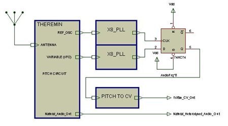
The difference is that, prior to obtaining audio from mixing the two HF waveforms, you have these two HF waveforms which have a difference frequency that gives (after mixing) the audio – and this fact makes it possible to obtain the audio* frequency multiplied by whatever one wants, and thereby reducing latency and eliminating other problems – This can only be done with theremins!
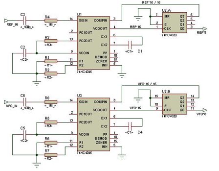
1b) The Phase Locked Loop (PLL):
The PLL, in its simplest implementation, is capable of multiplying an input frequency by some integer constant. Design of PLL circuits / systems can be horrendously complex if they are required to track wide ranging frequencies and stay in ‘lock’, but for use in multiplying the reference and variable oscillator frequencies from a theremin, they are nearly as simple to use as a 555 timer!
What is required is to multiply the frequencies of BOTH the reference and variable oscillators, and obtain the difference frequency AFTER these have been multiplied – doing this, one ends up the difference frequency being multiplied by the same constant.
You may ask: “Why not just multiply the audio frequency using a single PLL?” – the reason why this will not work (and therefore why only theremins can exploit the technique I describe) is that the same constraints as apply to pitch-voltage converters (latency) apply to PLL’s, and also that, to track an audio signal, the bandwidth which must be ‘captured’ by the PLL is huge – say 7 octaves.. Tracking a theremin VFO, the capture bandwidth is tiny (<< ¼ octave) as I describe below:
Lets take an example where the reference oscillator is running at 250kHz, and the variable oscillator has a 5kHz span, giving an audio output from null point (0Hz) to 5kHz.
We want (say) to have our CV track from 16Hz to the maximum 5kHz, and the minimum frequency our pitch-voltage converter (which requires 2 cycles to acquire the voltage) can accept is 100Hz, we can calculate:
Difference frequency before multiplication = 16 Hz
Required multiplier (for both Ref and VFO) = 8,
Reference frequency before multiplication = 250kHz
Reference frequency after multiplication = 2000k = 2MHz
VFO (variable oscillator) frequency before multiplication = 250kHz – 16Hz = 249.984kHz
VFO (variable oscillator) frequency after multiplication = 1999.872k = 1.999872MHz
Difference frequency of multiplied oscillators = 128 Hz.
If our difference frequency was 5kHz, and we stayed with a multiplier of 8, the reference oscillator frequencies stay the same, but VFO and difference frequencies become:
Difference frequency before multiplication = 5 kHz
VFO (variable oscillator) frequency before multiplication = 250 kHz – 5 kHz = 245 kHz
VFO (variable oscillator) frequency after multiplication = 1960.0 kHz = 1.96 MHz
Difference frequency of multiplied oscillators = 0.04 MHz = 40 kHz
It can be seen that:
The VFO PLL only needs to track a tiny deviation from its centre frequency (input frequency varies from 245 kHz to 250 kHz for a theremin having a 5kHz span, and the PLL could deal with a much greater frequency deviation, easily 10% or 25 kHz)
The frequency range fed to the pitch-voltage converter has been raised (multiplied) – this converter would need to be modified or re-designed to cater for the higher input frequencies.
The 16Hz frequency (theremin audio) can be resolved into a voltage in < 16ms if 2 complete (multiplied) audio cycles are used – but, in fact, this time can be at least halved if the PLL/ divider outputs a square wave with equal mark and space times, as all the required information is then contained in one ½ cycle.
Combining the above facts, it is possible to design the PLL so that the frequency presented to the pitch-voltage circuit can be reduced by one octave and the P-V circuit designed to work on half cycles.
To be continued..