A register switching “E-Pro like” Theremin.
 Fred Mundell Fundamental Designs Ltd. 2012
Reference is made to TW in this document, and some confusion may be caused because I mix links between TW and E-14. What appears here is a somewhat abreviated version of what appears here on TW http://www.thereminworld.com/Forums/T/28562/a-register-switching-e-pro-like-theremin?last=True
– I am not providing full schematics or PCB’s or anything like that.. I am providing information on the basic theory in enough depth, I believe, that an electronics engineer or competent electronics enthusiast who took the time to read and understand my notes, would be able to put the pieces (and missing pieces) together quite quickly, and from this be able to build a register switching Theremin.
I also wish to declare that this is NOT a copy of the EW-Pro.. I do not have access to an EW-Pro and have never reverse-engineered one.. I do not know if what I am doing is similar to how the EW-Pro operates, all I “Know” about the EW-Pro is that its audio is generated using mixed-signal techniques, and I believe (but have not confirmed) that it produces one primary waveform (triangle) from mixing square wave HF oscillator signals through an XOR gate followed by integrator (commonly called “digital” heterodyning, which, IMO, is incorrect – IMO it is Mixed-Signal heterodyning) , and from this waveform analogue techniques are used to change the waveform to the desired timbres.
I think my design could have some advantages over the E-Pro – In particular, I am generating ramp, triangle and Square wave (with adjustable M/S ratio) so obtaining a wide range of tones (because I have control of waveforms providing both odd and even harmonics) should be easier, also, more registers are possible because (with use of PLL’s) I can multiply as well as divide the frequencies.
I will not talk about the E-Pro anymore in this ‘disclosure’ – The main reason I mentioned it is because it is the best known ‘register switching’ theremin, and because people have expressed an interest in building something like an E-Pro in the past (here on TW).. And because the E-Pro has been discontinued without any replacement, leaving a huge hole for an instrument like this to replace it.
Before I get to the ‘nuts and bolts’, I must say that I am on a ‘knife edge’ about publishing this at all.. This project is the one I expected to be the most profitable, and I was intending to launch it at HO2011 – it was my top priority.. There is a voice in my head shouting “Don’t do it!!” – But I tend to ignore that voice, which is probably why I end up in the *** so often! LOL!
The other reason for my hesitance is that last time I “exposed” anything about the E- (oops, said I wouldn’t mention it again, LOL) I was semi-submerged for weeks in a pile of *** from infuriated thereminists who believed I had betrayed dear Bob Moog, and also de-valued their instruments. I regret that I may have appeared disrespectful to Bob – This was never my intent. It is impossible to say what the deceased would feel about things said or “exposed” after their death, one can only act on what one believes about them from ones limited contact with or exposure to their life. It was (and is) my opinion that Bob would not have wanted his creation to disappear, or that he would have wanted theremin development to be impeded by some “priests” guarding the “sanctity” of his work – It is Bob’s generosity in disclosing his ideas publicly and freely which got me where I am today – He inspired my interest in electronics and synthesis – But for him, I might have been a mathematician! (that’s a joke, BTW ;0)
And, finally : I retain whatever rights I can (copyright etc) on what I disclose here.. I am happy for people to use these ideas for their education, their own projects and to build their own instruments – But I would not be happy if someone took these ideas and manufactured instruments based on these ideas unless they contacted me first and gave me something (If I no longer exist, donating some of the profits to my children would be nice).
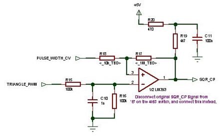
Some of the ideas and ‘sections’ of my “Plasma” (register switching theremin) are already published here on TW, and these include the >>Mixed Signal Theremin – Heterodyning and Waveshaping<< http://www.element14.com/community/thread/18199?tstart=0 Schematic and the discussion on PLL’s etc in the thread >> Fred’s Notebook – CV’s PLLs and more.. << http://www.element14.com/community/thread/18260?tstart=0 You need to read these comprehensively – if you cannot understand what is said there, you will not be able to build “Plasma” based on what I say here!
Not much in the way of schematics can be given.. As this is a mixed signal (logic level and analogue) design, I implemented most of the circuitry in custom IC’s (a couple of CY8C2964 PSoC’s in fact) – There is no reason to use PSoC’s for a simple “Plasma” ‘clone’ – the reason I used them was because (a) I wanted to hide my tricks (b) I had other functions which needed to be done, like “Wrong-side-of-null-point” indication and muting (see my Skywave H1 documentation ) http://www.element14.com/community/docs/DOC-46111/l/skywave-hipdf and the logic for pitch-voltage conversion, and (c) There are some extra things I am not telling anyone about yet (d) to save on PCB real estate.
It will take me more time that I have right now, to draw up the full schematics for the minimum ‘Plasma’ – And I do not want to publish the PSoC details / internal configuration yet, as this would still give me a big edge over any competitor who copied my designs, if I ever did get back to building theremins.
But what I provide should be enough:
Why a Register Switching Theremin?
If one wants to play more linear octaves with reasonable spacing between notes, a register switching theremin can allow you to do this – One can play about 4 octaves in a ‘perfectly’ linear area of the pitch field, and about another octave where the field may be somewhat distorted, and you can switch the registers so that the linear field is covering the registers you are playing.
The other factor is technical – It is extremely difficult to design, build and TUNE a theremin to give linearity over a length of (say) 70cm, and to compress 9 octaves into this field, even if equally spaced one would have quite a tight squeeze on notes. By switching registers, one makes it possible to utilize the linearity which is not too difficult to obtain, and to extend the note coverage without causing field compression.
The diagram below shows one of my Plasma breadboards response plots – this particular variant used oscillators based on the Silicon Chip / EPE designs, heavily modified – I was not happy with the stability of these oscillators, and use with a linearizing inductor (which produced these results) was highly unstable – Replacing these oscillators with better ones based on the EW gave much better results:
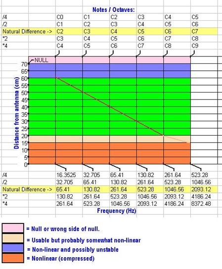
The S/C oscillators ran at ~ 460kHz , and they could have been divided down again to give coverage from 8Hz to 261Hz – with this (/8) divisor, the HF oscillators would have been divided down to 57.5 kHz, so the high frequency components could still be filtered away easily after heterodyning. There is a limit, however, on how many stages of division one can insert before one has problems cleaning up the heterodyned waveform.
Using oscillators running at ~ 250 kHz, I limited Plasma to /4, this gave plenty of headroom to for the filter (lowest unwanted frequency to be filtered is higher than 50 kHz).
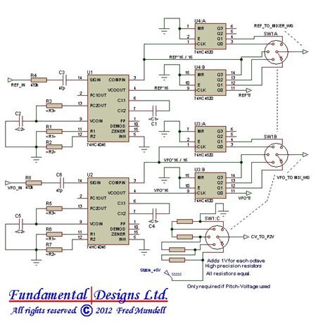
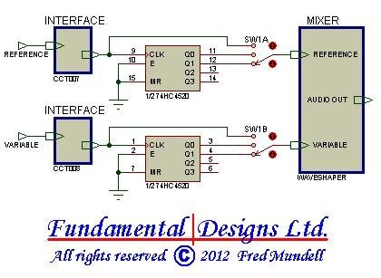
One can build a simple version of Plasma which does not use PLL’s and only has 3 ranges – the /4, /2, and ‘natural’ (/1).
In the following diagram/s, I show switches – this is just for speed and clarity – As everything is at logic level (I used 74HC family running at 5V, and PSoC running at 5V) one uses programmable dividers or data selectors to facilitate the “switching”.
You need to ‘isolate’ your oscillators from your logic – and you need to produce clean logic level square waves of the oscillator signals.. It is imperative that the interface / logic does not load the oscillators in any unacceptable way, as in, resistive load must be high, and capacitive load must be extremely low and unchanging. Depending on which oscillators or circuitry you are interfacing with, different techniques will need to be employed, but whatever oscillator you use, this interface needs to be carefully thought about!
- Interfacing to the SC/EPE designs is simple, as most of these are buffered. See my >>Skywave H1<< where I use a LM393 comparator, as an example.
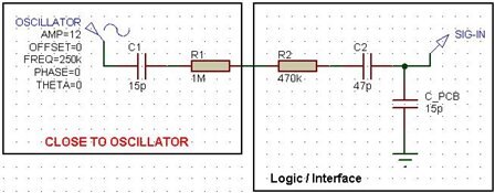
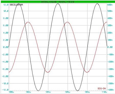
- Interfacing to the Moog EW oscillators should be reasonably simple – when I interfaced to them I used the SIG-IN pin of the 74HC4046 PLL, this pin accepts AC coupling and has a self-biasing input amplifier – The voltage from the EW oscillators is high (+/- 12V) so the signal level needs attenuating – this allows one to use the pin capacitance of the 4046 and board (about 10pF) and resistance between the oscillator and this pin to provide the attenuation.. I connected a 22p capacitor to the oscillator, this connected in series with a 1M resistor, and these components were mounted right at the oscillator.. I then ran a wire to my logic board which had a 470k resistor in series with a 22p capacitor which was connected to the SIG-IN pin. Prior to connecting to the SIG-IN pin, I tested the signal with my ‘scope (you cannot reliably probe the SIG-IN pin with a scope, as the probes capacitance is usually higher than the pin capacitance and additive) and had a signal level of 350mV. The SIG-IN pin requires 300mV, so this was in the right ball-park, and it worked.
The best bet is to buffer the oscillator signals with a voltage follower (BJT or FET) – But direct interfacing to a comparator in a similar way as I described for the HC4046 should be fine – giving the comparator some hysteresis is also a good idea.
This is shown in the simulation below:
And this is the block diagram – Circuits for the interface have been discussed above, circuit for the mixer / waveshaper are given Here, all you need to add are the audio processing (minimum an adjustable LPF) and volume control antenna and VCA.
 | |
 | |
 | |
 |